Inverter device and electric vehicle

a technology of inverter and electric vehicle, which is applied in the direction of vehicle sub-unit features, propulsion by batteries/cells, transportation and packaging, etc. it can solve the problems of increasing output voltage error, reducing the number of pwm pulses, and increasing the output voltage error of the inverter, so as to achieve stably controlled output voltage errors of the inverter circuit.

Active Publication Date: 2019-11-28
HITACHI ASTEMO LTD
View PDF0 Cites 0 Cited by
  • Summary
  • Abstract
  • Description
  • Claims
  • Application Information

AI Technical Summary

Benefits of technology

[0008]According to the embodiment of the present invention, the output voltage errors of the inverter circuit are reduced, and the motor is stably controlled until the motor rotates at high speed.

Problems solved by technology

Accordingly, when the inverter output frequency becomes high, the number of PWM pulses reduces and output errors of the inverter increase.
Further, the output voltage error increases in an overmodulation mode in which the inverter output voltage command exceeds the maximum output level (sine wave) of the inverter.

Method used


Image

  • Inverter device and electric vehicle
  • Inverter device and electric vehicle
  • Inverter device and electric vehicle

Examples


Embodiment Construction

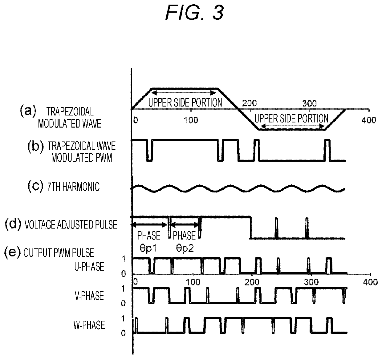
[0016]The present invention provides an inverter device that drives a semiconductor switch element to provide a high output power by PWM control in which the inverter device changes a pulse width of a PWM pulse at predetermined timing on an upper side of a trapezoidal wave in accordance with a phase of the trapezoidal wave, when trapezoidal wave modulation using a trapezoidal wave is performed in an overmodulation region having a modulation rate equal to or greater than a predetermined value. In the following, an embodiment of the present invention will be described by referring to the accompanying drawings.

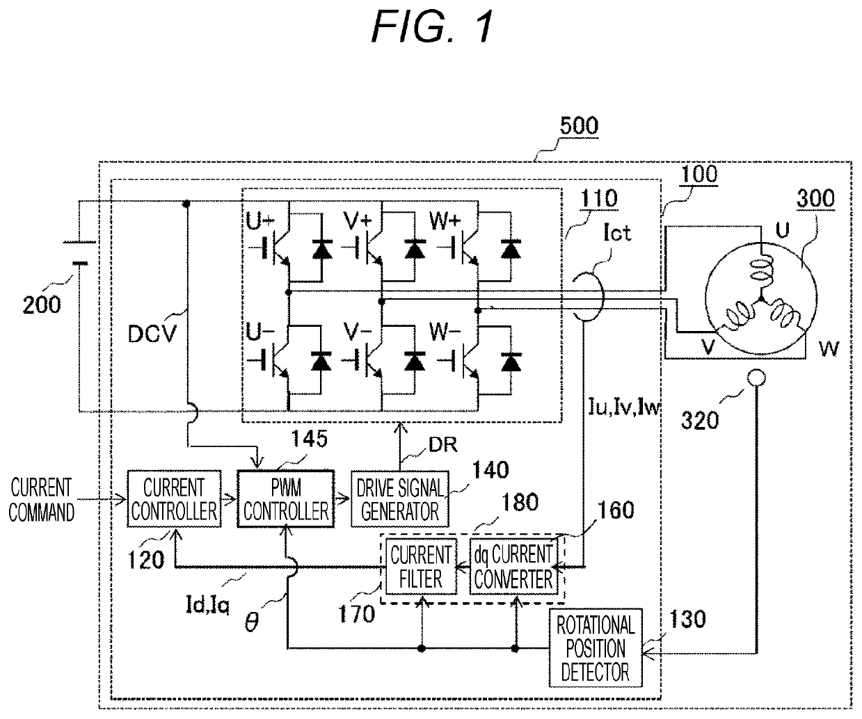
[0017]FIG. 1 is a block diagram illustrating a configuration of a motor device 500 including an inverter device 100 according to the present invention. The motor device 500 includes a motor 300 and the inverter device 100. The motor device 500 can be used to drive the motor 300 highly efficiently by detecting a mounting position error of a rotational position sensor of the motor ...


PUM


Abstract

An object of the present invention is to reduce output voltage errors of an inverter circuit and stably control a motor until the motor reaches high speed rotation. An inverter device includes a PWM controller that generates a PWM pulse for converting DC voltage to AC voltage in accordance with an output request of a motor, and an inverter circuit that converts the DC voltage to the AC voltage with the PWM pulse generated by the PWM controller and drives a motor. The PWM controller changes the pulse width of the PWM pulse at predetermined timing on the upper side of the trapezoidal wave when the trapezoidal wave modulation using the trapezoidal wave is performed in the overmodulation region.

Description

TECHNICAL FIELD[0001]The present invention relates to an inverter device and an electric vehicle.BACKGROUND ART[0002]Inverter driving devices that perform pulse-width modulation (PWM) control for driving motors often adopt an asynchronous PWM method that controls PWM by making the carrier frequency be constant with respect to variable output frequency of an inverter. Accordingly, when the inverter output frequency becomes high, the number of PWM pulses reduces and output errors of the inverter increase. Further, the output voltage error increases in an overmodulation mode in which the inverter output voltage command exceeds the maximum output level (sine wave) of the inverter.[0003]PTL 1 discloses a technique of generating PWM pulses in an angular section where the output voltage is linearly approximated about the zero cross point to minimize output voltage errors.CITATION LISTPatent Literature[0004]PTL 1: JP 2015-19458 ASUMMARY OF INVENTIONTechnical Problem[0005]In PTL 1, the PWM p...

Claims


Application Information

Patent Timeline
Patent Type & Authority Applications(United States)
IPC IPC(8): H02M7/5387H02P27/08
CPCB60Y2200/91B60Y2200/92B60K6/22H02M7/53871H02P27/08B60L50/60B62D5/04B60Y2400/61B60L2210/14B60L15/08B60L2210/40B62D5/046B60L50/61H02M7/53875H02M7/5395Y02T10/62Y02T10/64Y02T10/70Y02T10/72
Inventor AJIMA, TOSHIYUKIISOBE, JUNKITAKAOKA, MIDORIASHIDA, AKIHIROTAMURA, HIROSHI
Owner HITACHI ASTEMO LTD
Why Eureka
Try Eureka