Matrix convertor, power generation system, and method for converting power

Inactive Publication Date: 2016-03-31
YASKAWA DENKI KK
View PDF1 Cites 3 Cited by
  • Summary
  • Abstract
  • Description
  • Claims
  • Application Information

AI Technical Summary

Benefits of technology

The present patent is about a method for converting power using a power convertor with bidirectional switches. The method includes performing commutation control of the switches using a pattern with multiple steps. To reduce errors in the output voltage, a compensation amount is calculated and decreased based on the voltage of the output phases. The technical effect of this method is to improve the accuracy and stability of power conversion.

Problems solved by technology

Although the commutation control prevents short-circuiting between the input phases and prevents the output phases from going into open state, an error may be generated in the output voltage.

Method used


Image

  • Matrix convertor, power generation system, and method for converting power
  • Matrix convertor, power generation system, and method for converting power
  • Matrix convertor, power generation system, and method for converting power

Examples


Embodiment Construction

[0025]A matrix convertor, a power generation system, and a method for converting power according to embodiments will be described in detail below with reference to the accompanying drawings. The following embodiments are provided for exemplary purposes only and are not intended to limit the present disclosure.

1. Configuration of Matrix Convertor

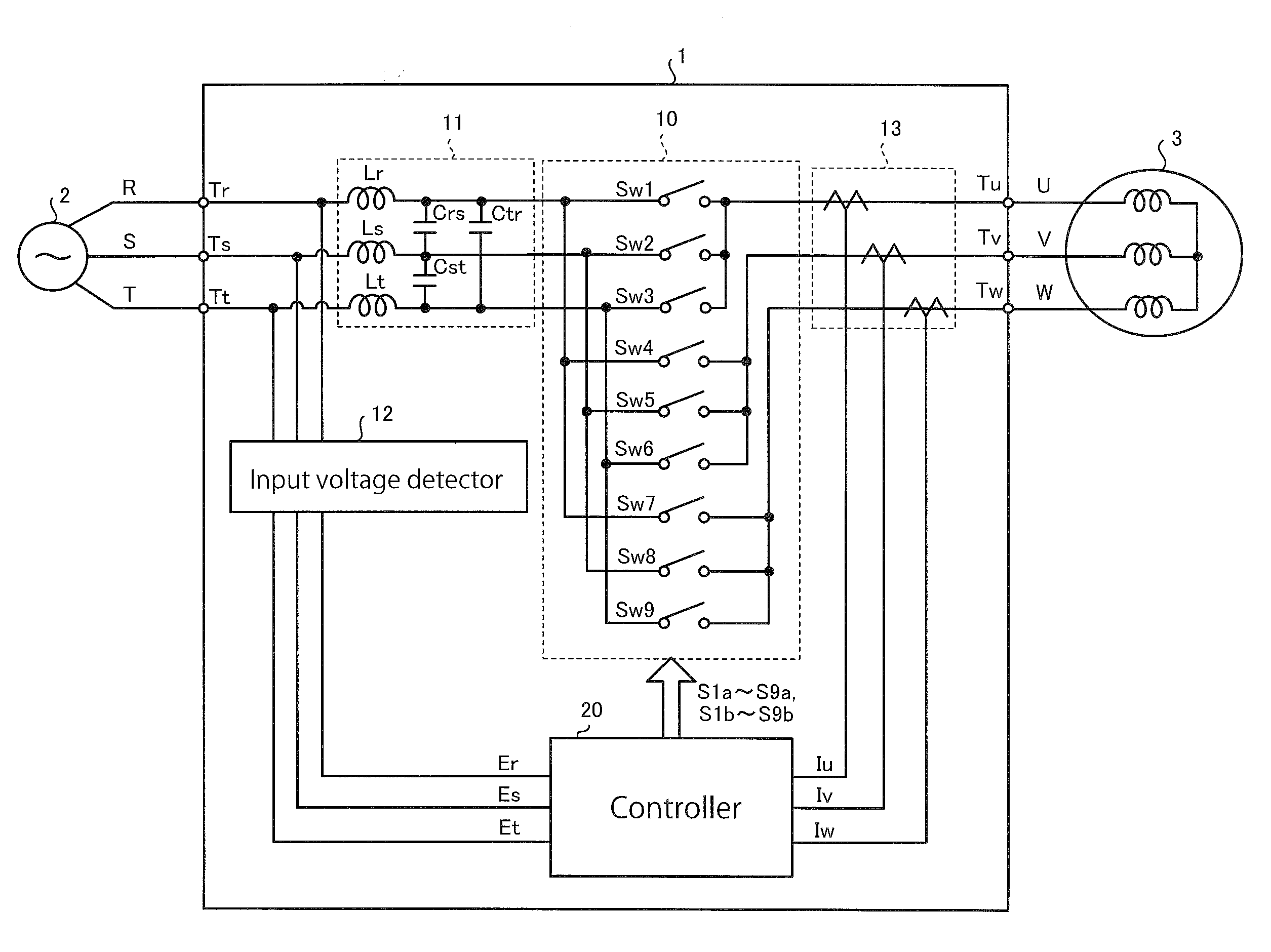
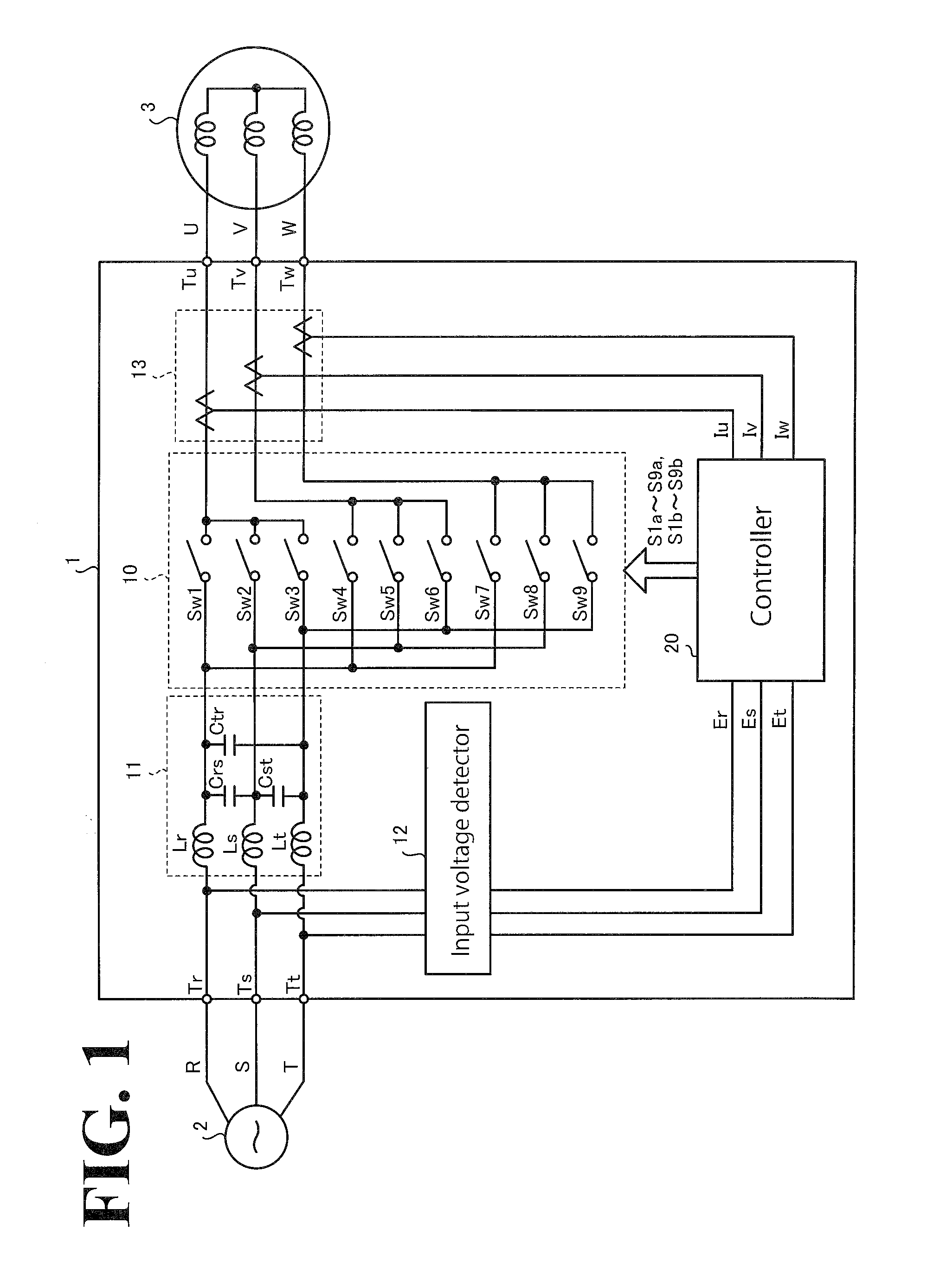
[0026]FIG. 1 is a diagram illustrating an exemplary configuration of a matrix convertor according to an embodiment. As illustrated in FIG. 1, the matrix convertor 1 according to this embodiment is disposed between the R phase, the S phase, and the T phase (which are examples of the plurality of input phases) of a three-phase alternating-current (AC) power source 2 (hereinafter referred to as “AC power source 2”) and the U phase, the V phase, and the W phase (which are examples of the output phases) of an AC device 3. Anon-limiting example of the AC power source 2 is a power system. Examples of the AC device 3 include, but are not limited to, ...


PUM


Abstract

A matrix convertor includes a power convertor, a commutation controller, an error compensator, and a compensation amount adjustor. The power convertor is disposed between input phases and output phases. The power convertor includes a plurality of bidirectional switches each including a plurality of switching elements. The commutation controller is configured to perform commutation control with respect to the plurality of switching elements of each of the plurality of bidirectional switches using a commutation pattern including a plurality of steps so as to switch connection between the input phases and the output phases through the power convertor. The error compensator is configured to calculate a compensation amount to decrease an error in an output voltage caused by the commutation control. The compensation amount adjustor is configured to decrease the compensation amount based on at least one voltage among voltages of the output phases.

Description

CROSS-REFERENCE TO RELATED APPLICATIONS[0001]The present application claims priority under 35 U.S.C. §119 to Japanese Patent Application No. 2014-195851, filed Sep. 25, 2014. The contents of this application are incorporated herein by reference in their entirety.BACKGROUND[0002]1. Field of the Invention[0003]The embodiments disclosed herein relate to a matrix convertor, a power generation system, and a method for converting power.[0004]2. Discussion of the Background[0005]Japanese Unexamined Patent Application Publication No. 2004-7929 and Japanese Unexamined Patent Application Publication No. 2007-82286 each disclose a matrix convertor that includes a plurality of bidirectional switches to connect input phases to output phases. The matrix convertor controls the bidirectional switches to directly switch the voltages of the input phases so as to output desired voltages and frequencies to the output phases. When the matrix convertor is connected between a power system and a power gene...

Claims


Application Information

Patent Timeline
IPC IPC(8): H02M5/293
CPCH02M2005/2932H02M5/293H02M5/297H02M5/2932
Inventor YAMAZAKI, AKIRAEBISU, JOJI
Owner YASKAWA DENKI KK
Why Eureka
Try Eureka