
Method of locating a source of pulses in a dispersive medium

Active Publication Date: 2016-11-10
INSTITUT NAT POLYTECHN DE GRENOBLE
View PDF2 Cites 2 Cited by
  • Summary
  • Abstract
  • Description
  • Claims
  • Application Information

AI Technical Summary

Benefits of technology

The patent describes a method for locating a pulse source in a dispersive medium using sensors. The method involves detecting pulses at each sensor, creating a phase diagram for each pair of sensors, and calculating the ratio between the distances of each sensor to the source. This ratio is used to determine the direction of the pulse in the medium. The method can be used in both guided and electric cable environments, and takes into account the effects of bandpass filters and spectral distance calculations. The technical effects of the patent include improved accuracy in locating the source of pulses in a dispersive medium.

Problems solved by technology

As an example, in an electric cable, a defect in the cable isolation may result in the occurrence of parasitic electric discharges, each discharge causing the generation of a pulse having a duration, or width, generally shorter than 1 μs.
An error as to the exact position of the pulse source may result in taking action on a wrong cable portion and in having to repeat the maintenance operation.

Method used


Image

  • Method of locating a source of pulses in a dispersive medium
  • Method of locating a source of pulses in a dispersive medium
  • Method of locating a source of pulses in a dispersive medium

Examples


Embodiment Construction

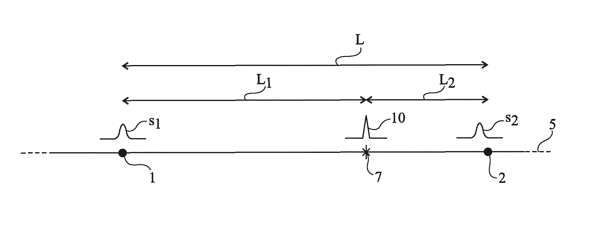
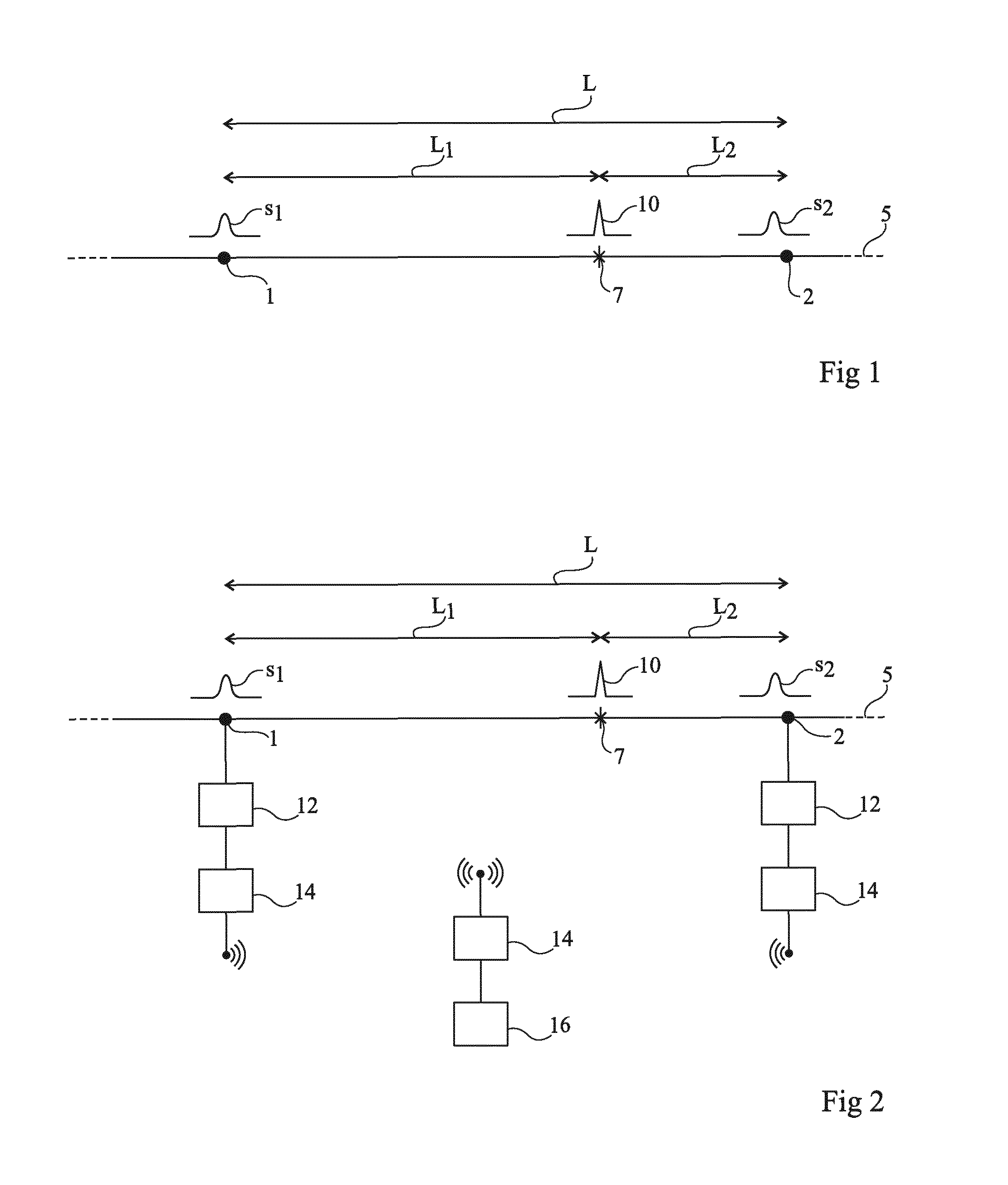
[0033]The embodiments described in detail hereafter aim at locating a source of electric pulses corresponding to electric discharges at one point of an electric cable. More generally, the method applies to the locating of any type of pulse source in any type of dispersive medium, be it guided or not. Another example of a guided dispersive medium is a water pipe. In this case, the pulses to be detected are not electric pulses but overpressure pulses. In the case of a non-guided dispersive medium, three sensors at least are used and the position of the pulse source is determined by triangulation based on the ratios between the distances from the source to each of the sensors. An example of a non-guided dispersive medium is a stressed mechanical part where internal breakage areas are desired to be located, the sensors then being vibration sensors or sound sensors.

[0034]FIG. 2 schematically illustrates an embodiment of a device for detecting a source of electric pulses in an electric ca...


PUM


Abstract

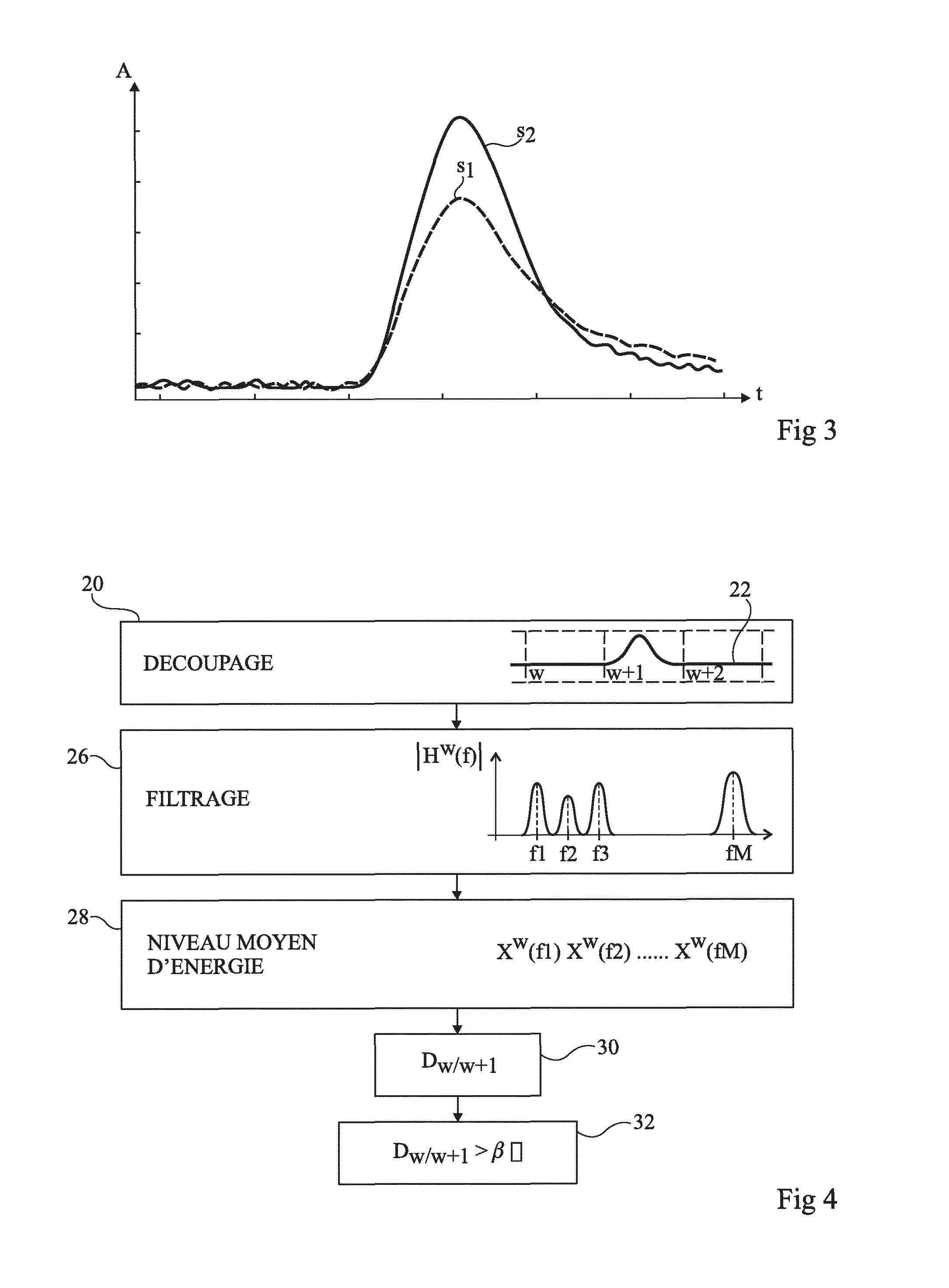
The invention relates to a method of locating in a dispersive medium (5) a source (7) of pulses (s1, s2) by at least one pair of sensors (1, 2), the method comprising the following steps: at the level of each sensor (1, 2), detecting a pulse (s1, s2) originating from the source (7); for each of said pulses, constructing a phase diagram on the basis of N vectors of which the co-ordinates correspond to the amplitude of the pulse (s1, s2) at successive sampling instants ti; and for each pair of sensors, calculating the ratio between the distances L1 and L2 of each sensor from the source through the formula (I) where (II) and (III) are the norms of the vectors (IV) and (V) of the phase diagrams corresponding to the pulses detected by the sensors (1, 2).L1L2=∑i=1Nr1(ti)→ / ∑i=1Nr2(ti)→(I)r1(ti)→(II)r2(ti)→(III)r1(ti)→(IV)r2(ti)→(V)

Description

CROSS-REFERENCE TO RELATED APPLICATIONS[0001]The present application is a National Stage of PCT International Application Serial Number PCT / EP2015 / 050106, filed Jan. 6, 2015, claims priority under 35 U.S.C. §119 of France, patent application Ser. No. 14 / 50348, filed Jan. 16, 2014, the disclosures of which are incorporated by reference herein.BACKGROUND[0002]The present disclosure relates to a method for locating a pulse source in a dispersive medium.DISCUSSION OF RELATED ART[0003]In carrier lines, for example, for electric energy, water, or data, different phenomena may result in the generation of pulses at one point of the lines. It is then desired to detect and to locate the area from which the pulses originate.[0004]As an example, in an electric cable, a defect in the cable isolation may result in the occurrence of parasitic electric discharges, each discharge causing the generation of a pulse having a duration, or width, generally shorter than 1 μs.[0005]Locating the pulse sourc...

Claims


Application Information

Patent Timeline
IPC IPC(8): G01R31/08
CPCG01R31/088G01R31/083G01R31/08
Inventor IOANA, CORNEL
Owner INSTITUT NAT POLYTECHN DE GRENOBLE
Learn More