Thermal flowmeter and flow rate compensation method

Active Publication Date: 2019-01-31
YAMATAKE HONEYWELL CO LTD
View PDF2 Cites 0 Cited by
  • Summary
  • Abstract
  • Description
  • Claims
  • Application Information

AI Technical Summary

Benefits of technology

The present disclosure provides a thermal flowmeter and a flow rate compensation method that can improve responsiveness to changes in the flow rate. The power measurement is compensated based on the temperature gradient and a known value when there is no fluid present in the pipe. The flow rate of the measurement target fluid is calculated based on the compensated power. This compensation method ensures accurate flow rate measurement even when the thermal resistive elements are not directly exposed to the fluid.

Problems solved by technology

This results in an increased error in the calculated flow rate, which is an issue.

Method used


Image

  • Thermal flowmeter and flow rate compensation method
  • Thermal flowmeter and flow rate compensation method
  • Thermal flowmeter and flow rate compensation method

Examples


Embodiment Construction

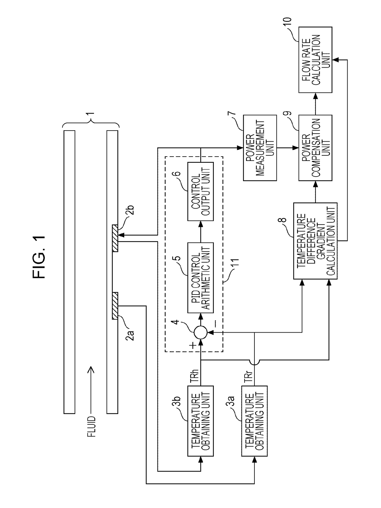
[0014]Hereinafter, an embodiment of the present disclosure will be described with reference to the drawings. FIG. 1 is a block diagram illustrating a configuration of a thermal flowmeter according to an embodiment of the present disclosure. The thermal flowmeter includes a pipe 1, thermal resistive elements (heaters) 2a and 2b, temperature obtaining units 3a and 3b, a subtractor 4, a PID control arithmetic unit 5, a control output unit 6, a power measurement unit 7, a temperature difference gradient calculation unit 8, a power compensation unit 9, and a flow rate calculation unit 10. The pipe 1 is formed of, for example, glass and allows a measurement target fluid to flow therethrough. The thermal resistive element 2a is formed of, for example, platinum and disposed on the pipe 1, and the thermal resistive element 2b is formed of, for example, platinum and disposed on the pipe 1 downstream relative to the thermal resistive element 2a. The temperature obtaining unit 3a obtains the te...


PUM


Abstract

A thermal flowmeter includes: a first thermal resistive element disposed on a pipe and sensing a first temperature of a fluid; a second thermal resistive element disposed on the pipe downstream relative to the first thermal resistive element and sensing a second temperature thereof; a control unit causing the second thermal resistive element to generate heat so that the second temperature is kept higher than the first temperature by a predetermined value; a power measurement unit measuring a power supplied to the second thermal resistive element; a temperature difference gradient calculation unit calculating a gradient of a difference between the second and first temperatures; a power compensation unit compensating the measured power based on the gradient of the difference and a value of the power when no fluid is in the pipe; and a flow rate calculation unit calculating a flow rate of the fluid based on the compensated power.

Description

CROSS-REFERENCE TO RELATED APPLICATIONS[0001]The present application is based on and claims priority to Japanese Application No. 2017-147621, filed Jul. 31, 2017, the entire contents of which are incorporated herein by reference.BACKGROUND1. Field of the Disclosure[0002]The present disclosure relates to a thermal flowmeter that measures the temperature of a fluid at two points, namely, an upstream point and a downstream point, of a pipe, controls a heater so as to keep the difference between the temperatures at the two points constant, and calculates the flow rate of the fluid from a power that is supplied to the heater.2. Description of the Related Art[0003]A thermal flowmeter according to the related art has a structure in which a heater and temperature sensors are disposed on the exterior of a pipe that constitutes a flow passage for a liquid so that the heater and the temperature sensors are not directly exposed to the liquid to avoid, for example, corrosion due to the liquid (s...

Claims


Application Information

Patent Timeline
IPC IPC(8): G01F1/696
CPCG01F1/6965G01F1/69G01F25/10G01F1/6847G01F1/696
Inventor YANAGAWA, YUUSEIYAMAZAKI, YOSHIOMATSUNAGA, SHINSUKEHASEBE, WATARU
Owner YAMATAKE HONEYWELL CO LTD
Why Eureka
Try Eureka