
Imaging apparatus, imaging method, and program

Inactive Publication Date: 2010-04-08
SONY CORP
View PDF11 Cites 33 Cited by
  • Summary
  • Abstract
  • Description
  • Claims
  • Application Information

AI Technical Summary

Benefits of technology

[0020]It is preferred that the image signal processor performs block matching at the boundaries created by arranging multiple selected ones of the images in such a way that the selected images overlap with each other along the respective boundaries, combines the selected images along the respective boundaries to extract a predetermined parameter, performs block matching at all the boundaries of the images having been combined based on the parameter, evaluates the block matching results for all the boundaries simultaneously and in parallel, and updates the direction of the optical axis in such a way that errors at all the boundaries decrease so that the combination is performed in such a way that the errors are reduced.

Problems solved by technology

Therefore, when positional information is produced only from the information obtained from the attitude sensor, the resultant panoramic photograph could be too rough to look at.

Method used


Image

  • Imaging apparatus, imaging method, and program
  • Imaging apparatus, imaging method, and program
  • Imaging apparatus, imaging method, and program

Examples


Embodiment Construction

[0051]An embodiment of the invention will be described below with reference to the drawings.

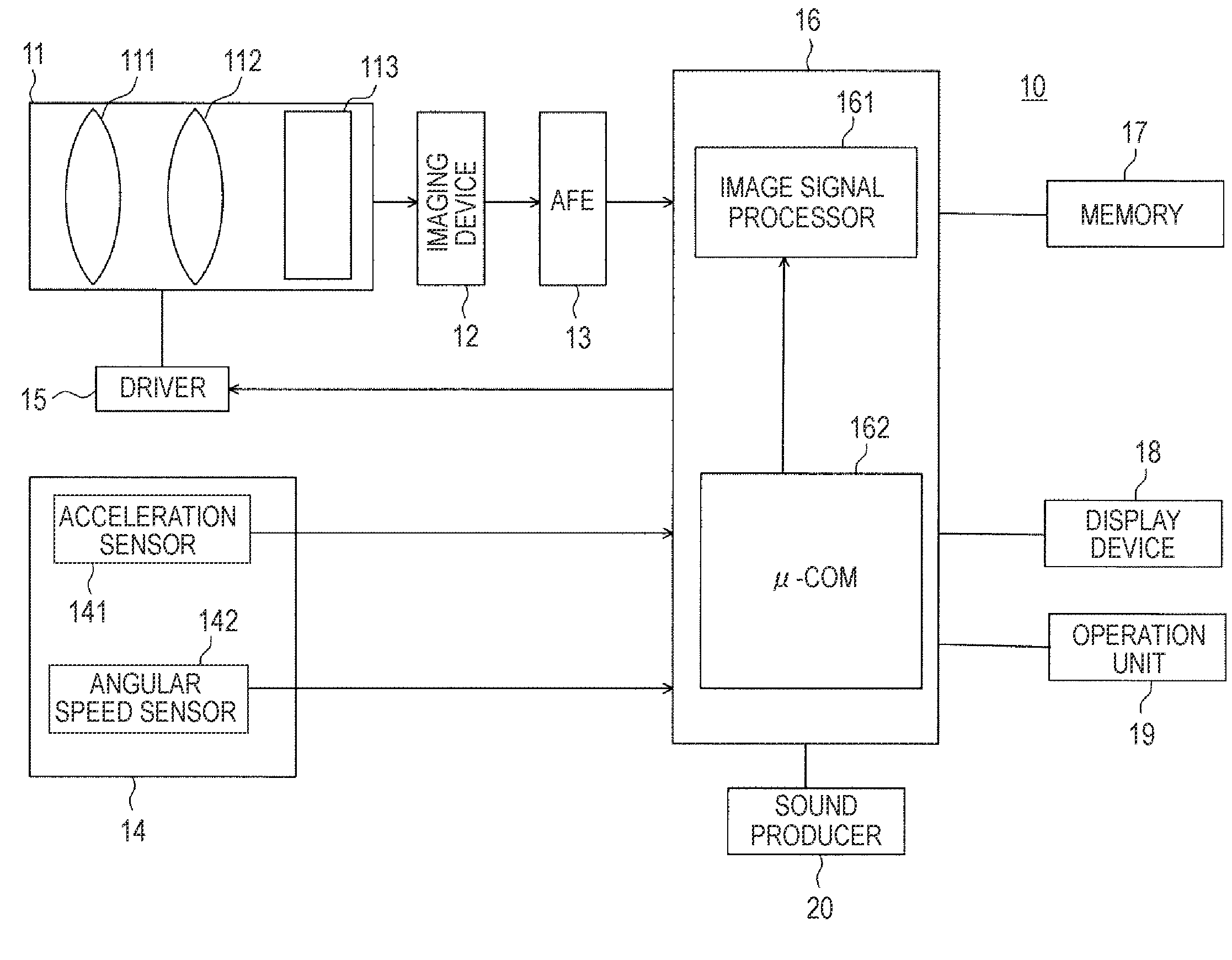
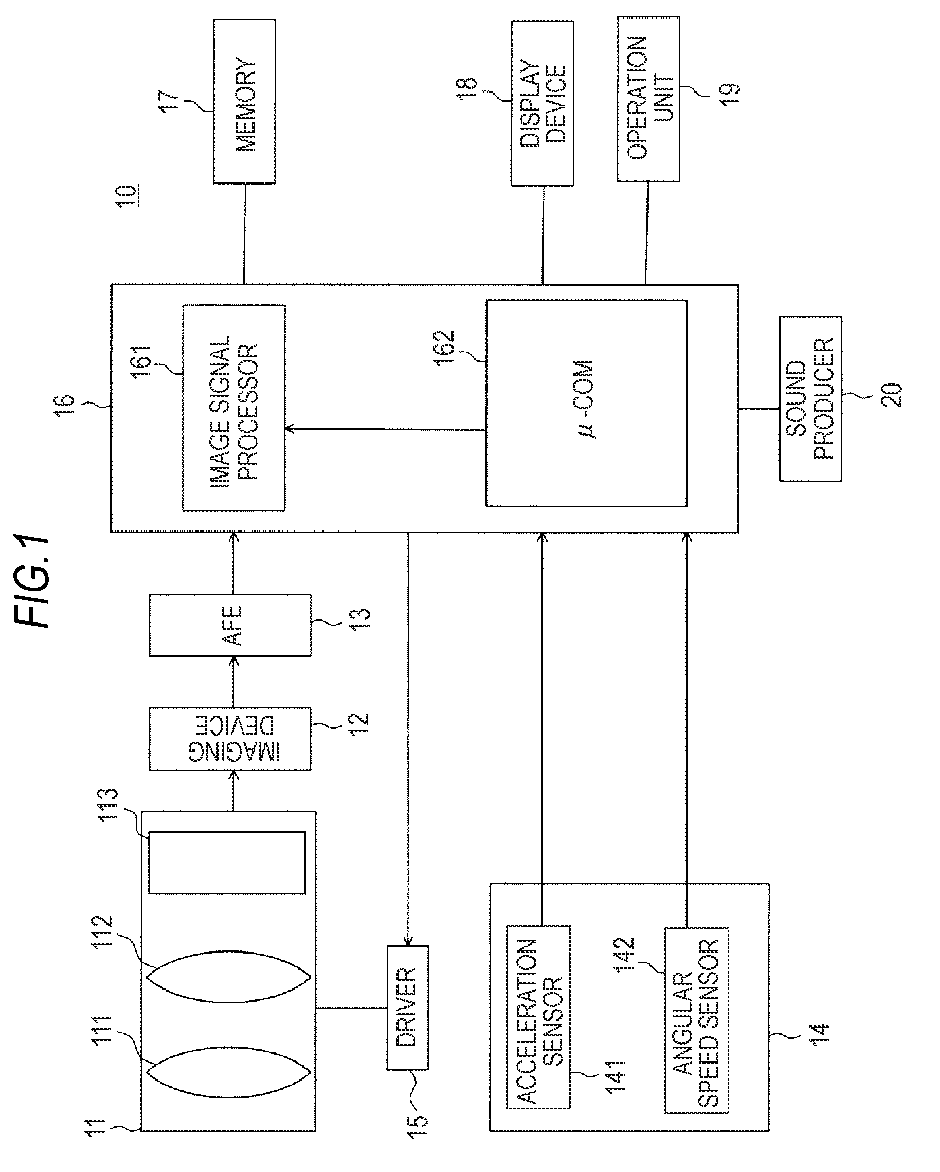
[0052]FIG. 1 is a block diagram showing an example of the configuration of a camera apparatus as an imaging apparatus according to the embodiment of the invention.

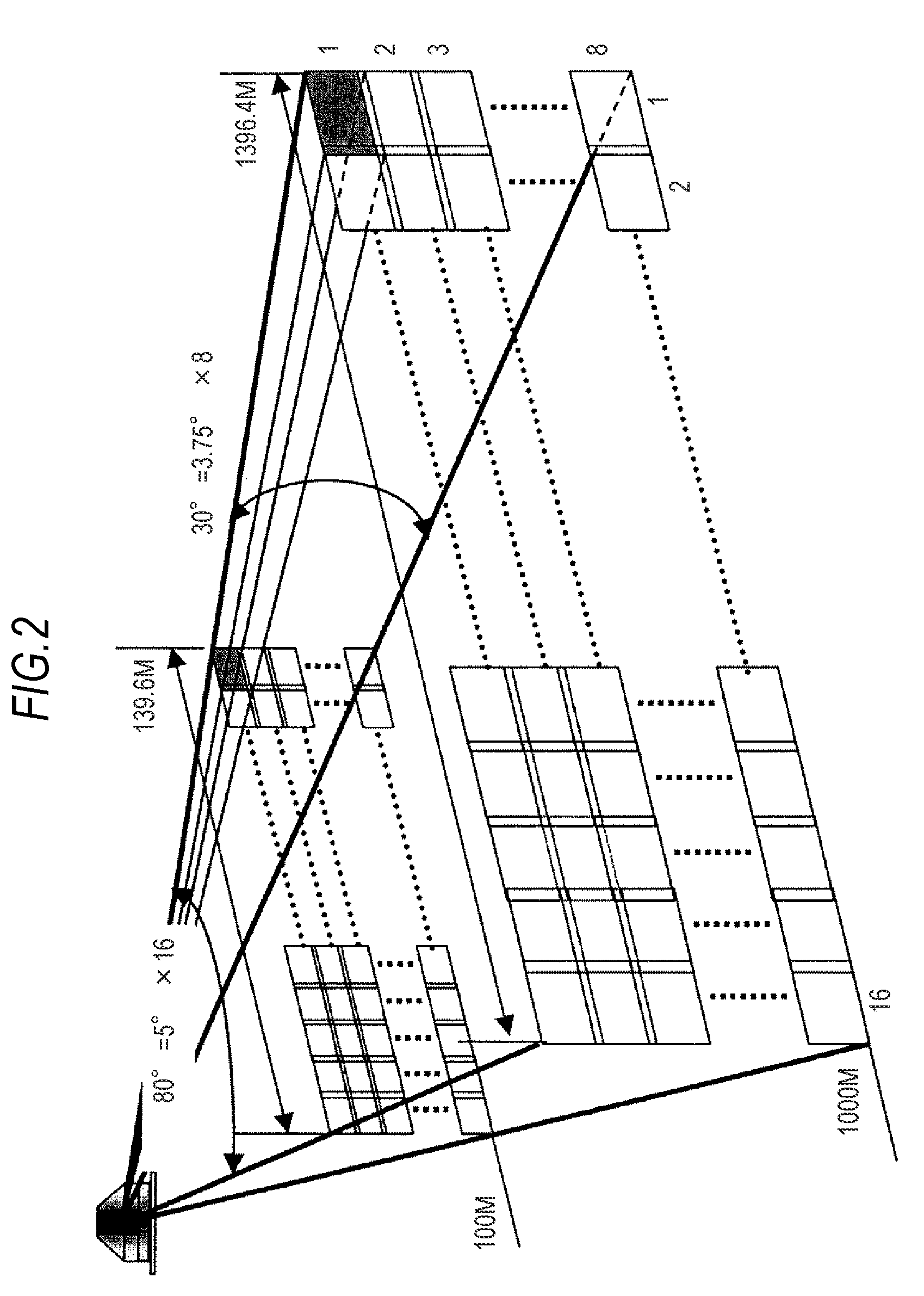
[0053]The camera apparatus 10 can produce, for example, as shown in FIG. 2, a large number of images (16×8=128 in FIG. 2) captured from a single point by automatically or manually changing the imaging direction multiple times.

[0054]The camera apparatus 10 is configured to accurately and seamlessly combine a large number of images, for example, several thousands of images, to form what is called a panoramic image.

[0055]That is, the camera apparatus 10 has a function of creating a panoramic picture based on images captured by swinging a digital camera in which a solid-state imaging device, for example, a CMOS image sensor (CIS), is incorporated at a high speed in the longitudinal or transverse direction.

[0056]The camera apparatus 10 a...


PUM


Abstract

An imaging apparatus includes: an imaging device capturing a subject image through an optical system; an image signal processor having a function of combining multiple captured images into a single image, the images being captured during the period when the imaging apparatus is moved; an attitude sensor providing information on the attitude of the imaging apparatus; and a control unit processing the information from the attitude sensor and performing coordinated control on the processed result of the attitude information and the processed result from the image signal processor, wherein the image signal processor uses image recognition to determine the relative positional relationship between adjacent images, and the control unit determines the positional relationship between adjacent images based on an initial value of the attitude information, directional data and a relative positional relationship determined by the image signal processor, and judges whether or not the determined result is correct.

Description

BACKGROUND OF THE INVENTION[0001]1. Field of the Invention[0002]The present invention relates to an imaging apparatus, an imaging method, and a program having a function of combining multiple images.[0003]2. Description of the Related Art[0004]When a camcorder, a digital still camera, or any other suitable apparatus is used to perform panorama imaging, it is necessary to keep the camera stationary whenever an image is captured, or it is necessary to move the camera slowly so that images are not blurred when the camera is moved and images are captured at the same time.[0005]In the latter case, a high-speed shutter is also necessary to capture images.[0006]In contrast, Japanese Patent No. 3,928,222 proposes a method for capturing images while moving a camera rapidly with the image resolution maintained.[0007]In the technique proposed in Japanese Patent No. 3,928,222, the direction in which the camera is moved and the angular speed at which the camera is moved are detected and the opti...

Claims


Application Information

Patent Timeline
IPC IPC(8): H04N7/00G06K9/00H04N5/232
CPCG06T7/003H04N5/23232H04N2101/00H04N5/2329H04N5/23238G06T7/337H04N23/951H04N23/698H04N23/689
Inventor YAMASHITA, NORIYUKIKUNIKANE, KENTARO
Owner SONY CORP
Learn More