Angle computation method and apparatus for variable reluctance resolver

a computation method and resolver technology, applied in the direction of acceleration measurement using interia forces, code conversion, instruments, etc., can solve the problems of complex and time-consuming process of creating tables, increase output errors, and deterioration of angle detection accuracy, so as to achieve the effect of reducing errors

Inactive Publication Date: 2007-03-06
MINEBEA CO LTD
View PDF5 Cites 1 Cited by
  • Summary
  • Abstract
  • Description
  • Claims
  • Application Information

AI Technical Summary

Benefits of technology

[0015]In view of the foregoing, an object of the present invention is to provide an angle computation method for a variable reluctance resolver, which method can obtain output voltages and an angle with minimized errors, through computation processing, on the basis of error-containing output voltages of the resolver.
[0020](1) The error is corrected in consideration of offsets of the output voltage of the SIN voltage output coil and the output voltage of the COS voltage output coil. An angle is obtained, while Vsin−A is used as an offset-corrected output voltage of the SIN voltage output coil for extracting sine output voltage, and Vcos−C is used as an offset-corrected output voltage of the COS voltage output coil for extracting cosine output voltage. Thus, errors in the output voltages are reduced, and angle detection accuracy is improved.
[0022] The above values are obtained, and then an angle is obtained, while Vsin−A is used as an output voltage of the SIN voltage output coil for extracting the sine output voltage, and K(Vcos−C) is used as an output voltage of the COS voltage output coil for extracting the cosine output voltage. Thus, errors in the output voltages are reduced, and the angle detection accuracy is improved.
[0023](3) The error is corrected in consideration of a shift from the zero point, the offsets, and a difference in amplitude between the output voltage of the SIN voltage output coil and the output voltage of the COS voltage output coil.θSINPHASE=sin−1(VSINOFFSET / VSINAMP)≅VSINOFFSET / VSINAMPThe above value is obtained, and then an angle is obtained, while Vsin−A is used as an output voltage of the SIN voltage output coil for extracting the sine output voltage, and K(Vcos−C) is used as an output voltage of the COS voltage output coil for extracting the cosine output voltage. Subsequently, the position shift is corrected by use of the angle θSINPHASE. Thus, errors in the output voltages are reduced, and the angle detection accuracy is improved.
[0052]The present invention can eliminate error factors from the output voltages of the output coils of the resolver to thereby improve the angle detection accuracy.

Problems solved by technology

However, because of transformation ratio of resolver outputs, short circuits of output coils, run-out of the rotor, variation in magnetic characteristics among stators, variation in coils among stators, and other factors, output error increases, and an accuracy of angle detection deteriorates.
The method of obtaining proper correction values with reference to such a correction reference table has a drawback in that the table must be re-created in accordance with the details of an error, and the procedure of creating the table is complicated and time consuming.
When, as in the conventional technique, an angle is computed from such output voltages, computation errors are produced under the influence of the DC components A and C.
However, since the number of turns cannot be increased infinitely, in some cases, the adjustment cannot reduce to zero the values of the terms “A” and “C.” Moreover, the number of turns does not necessarily become the same among individual resolvers, because of variation thereamong.

Method used


Image

  • Angle computation method and apparatus for variable reluctance resolver
  • Angle computation method and apparatus for variable reluctance resolver
  • Angle computation method and apparatus for variable reluctance resolver

Examples


example 1

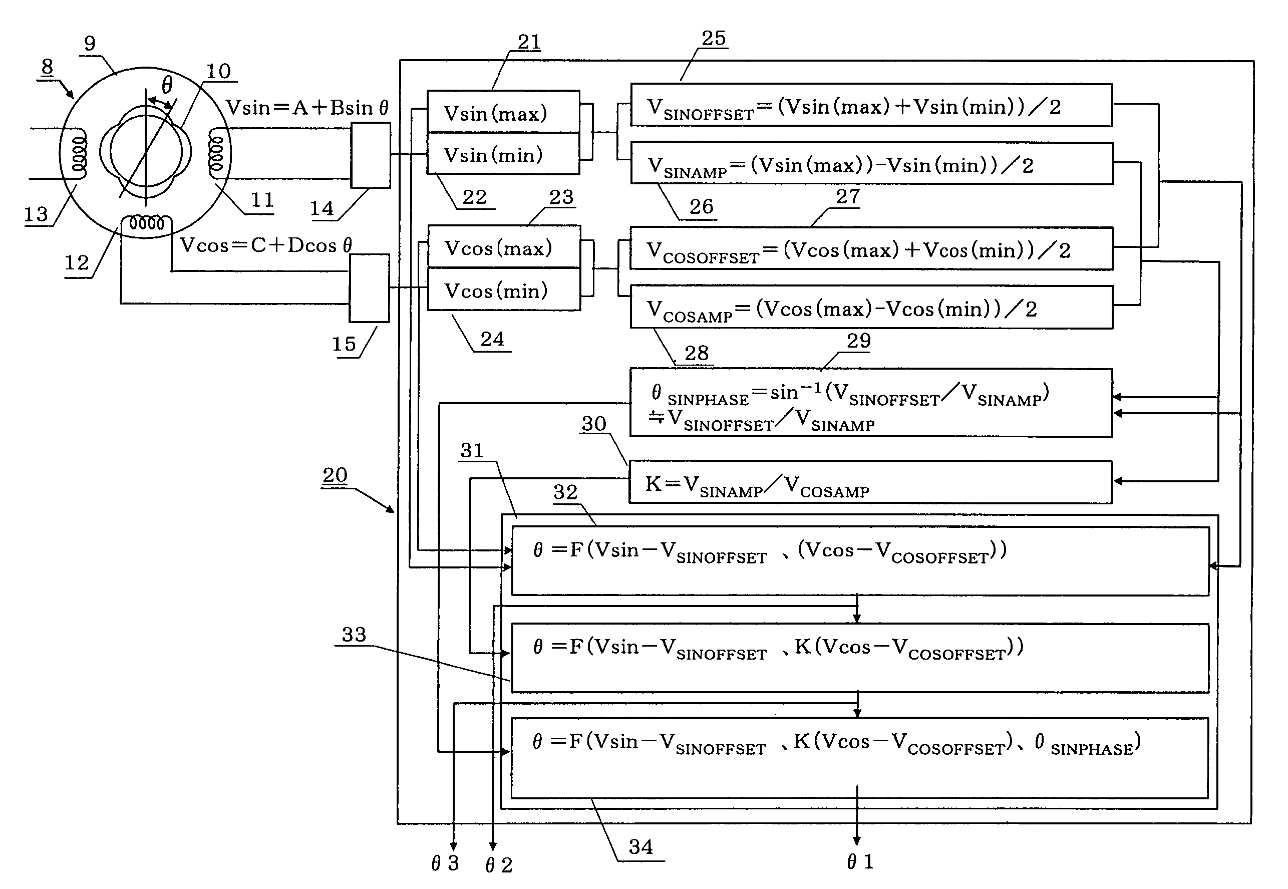
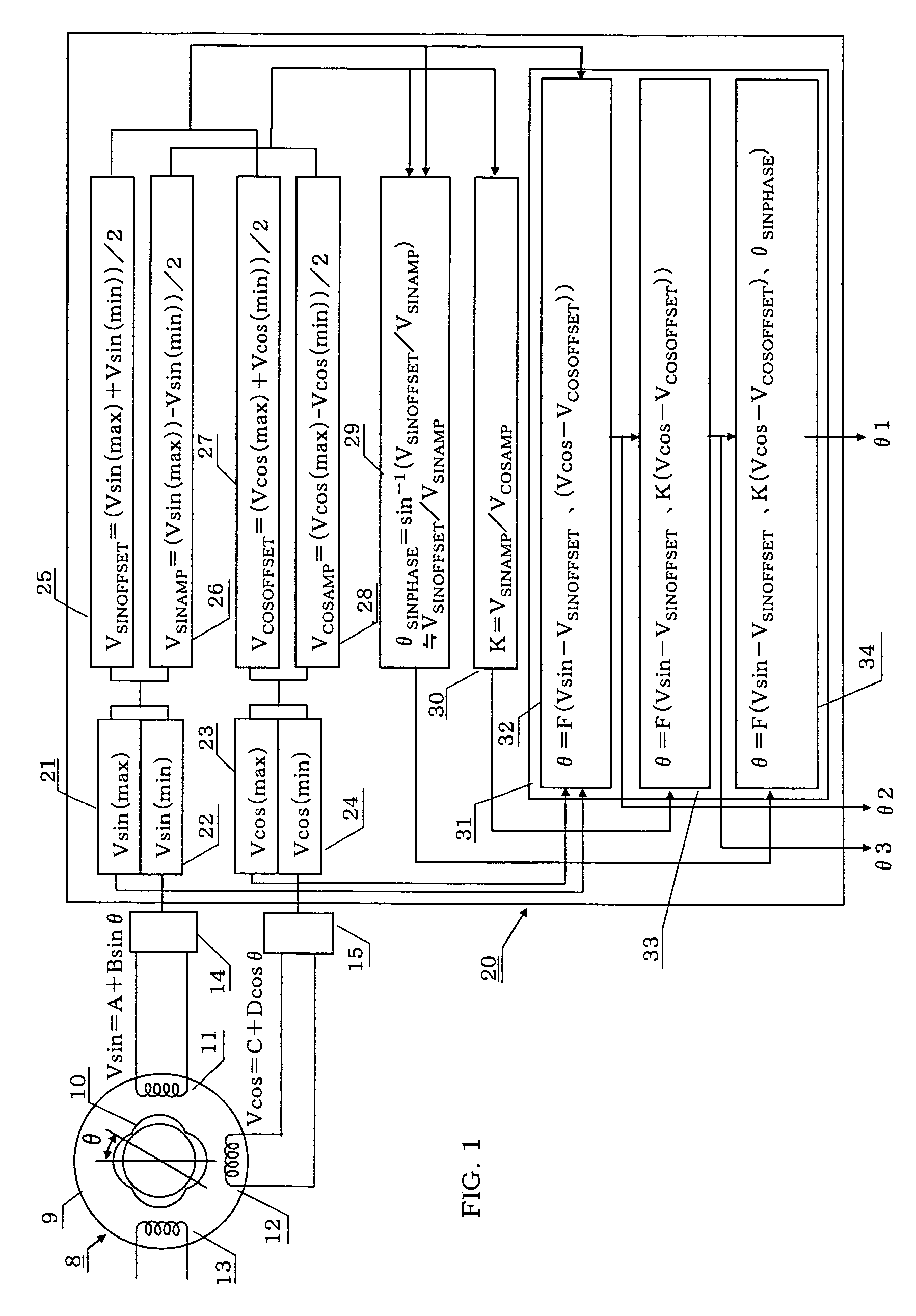
[0128]FIG. 1 is a block diagram of an angle computation apparatus for a VR resolver according to the present invention.

[0129]A VR resolver 8 includes a stator 9 and a rotor 10.

[0130]A SIN voltage output coil 11, a COS voltage output coil 12, and an excitation coil 13 are provided on respective magnetic pole teeth of the stator 9. When the rotary shaft is rotated with the excitation coil 13 excited, a voltage output from the SIN voltage output coil 11 is detected by means of an output voltage detector 14. Similarly, a voltage output from the COS voltage output coil 12 is detected by means of an output voltage detector 15.

[0131]Outputs of the output voltage detectors 14 and 15 are input to an angle computation apparatus 20, which outputs an angle signal θ through performance of necessary computation processing.

[0132]The angle computation apparatus 20 is formed of a microcomputer which consists of a CPU (central processing unit), memory, input / output interfaces, etc., and executes the ...

example 2

[0149]The offset values may be obtained through the following steps.

[0150]For the SIN voltage output coil for extracting the sine output voltage, an offset value for the sine output voltage is obtained from the deviation between an integral value of a positive output voltage and an integral value of a negative output voltage. Similarly, for the COS voltage output coil for extracting the cosine output voltage, an offset value for the cosine output voltage is obtained from the deviation between an integral value of a positive output voltage and an integral value of a negative output voltage. Subsequently, the above-described correction of offset voltages (DC components) is performed by use of these offset values.

[0151]In this case as well, the apparatus can eliminate error components from the output voltages output from the resolver, to thereby improve the accuracy of angle detection.


PUM


Abstract

In an angle computation method and apparatus for a variable reluctance resolver, the maximum values Vsin(max) and Vcos(max) of sine and cosine output voltages in respective positive value ranges and the minimum values Vsin(min) and Vcos(min) of the sine and cosine output voltages in respective negative value ranges are extracted, and on the basis of these values, offset values, amplitude values, sin-cos voltage ratio, and a zero-point correction value are obtained in accordance with the following equations:VSINOFFSET=(Vsin(max)+Vsin(min)) / 2VSINAMP=(Vsin(max)−Vsin(min)) / 2θSINPHASE=sin−1(VSINOFFSET / VSINAMP)≅VSINOFFSET / VSINAMPVCOSOFFSET=(Vcos(max)+Vcos(min)) / 2VCOSAMP=(Vcos(max)−Vcos(min)) / 2K=VSINAMP / VCOSAMPOn the basis of the thus-obtained values, an angle θ is obtained in accordance with the following equation:F(Vsin−VSINOFFSET, K(Vcos−VCOSOFFSET), θSINPHASE)=θ.

Description

BACKGROUND OF THE INVENTION[0001]1. Field of the Invention[0002]The present invention relates to an angle computation method for a variable reluctance resolver (hereinafter VR resolver) which enables an accurate angular detection even when unignorable errors arise from various portions of the resolver, and to an angle computation apparatus for performing the angle computation method.[0003]2. Description of the Related Art[0004]There exist a variety of resolvers, which differ in terms of operation scheme, coil structure, wiring, etc. For example, a VR resolver of a one phase excitation / two phase output includes a stator on which are wound an excitation coil, a SIN voltage output coil, and a COS voltage output coil; and a rotor which has a plurality of salient poles and which, upon rotation within the stator, changes the gap permeance between the two output coils in accordance with a sine function, which is a function of a rotational angle θ. The SIN voltage output coil outputs a sine...

Claims


Application Information

Patent Timeline
Patent Type & Authority Patents(United States)
IPC IPC(8): H03M7/00G01D5/245G01D3/02G01D5/20G01D5/244H02K24/00
CPCG01D5/2046G01D5/2449G01D5/2448G01D5/24452G01D18/001
Inventor KOBAYASHI, MASAHIRO
Owner MINEBEA CO LTD
Why Eureka
Try Eureka