PWM rectifier having de-coupled power factor and output current control loops

Inactive Publication Date: 2002-04-02
ROCKWELL AUTOMATION TECH
View PDF5 Cites 149 Cited by
  • Summary
  • Abstract
  • Description
  • Claims
  • Application Information

AI Technical Summary

Problems solved by technology

This makes it difficult to stabilize the system if the drive operates at a frequency which is close to the resonant frequency.
The situation becomes even worse when the motor is unloaded since the inverter output current in this case is minimal whereas the resonant current flowing between the capacitor and the motor magnetizing inductance is substantial.
A similar resonance problem also exists when a PWM rectifier is employed in the drive to provide direct current to the CSI from a power source.
Unfortunately it is difficult to measure the system impedance accurately, which complicates the design of a compensating filter.
In addition, even when the resonance frequency is not close to any characteristic harmonic of the rectifier, undesired oscillations will also

Method used


Image

  • PWM rectifier having de-coupled power factor and output current control loops
  • PWM rectifier having de-coupled power factor and output current control loops
  • PWM rectifier having de-coupled power factor and output current control loops

Examples


Embodiment Construction

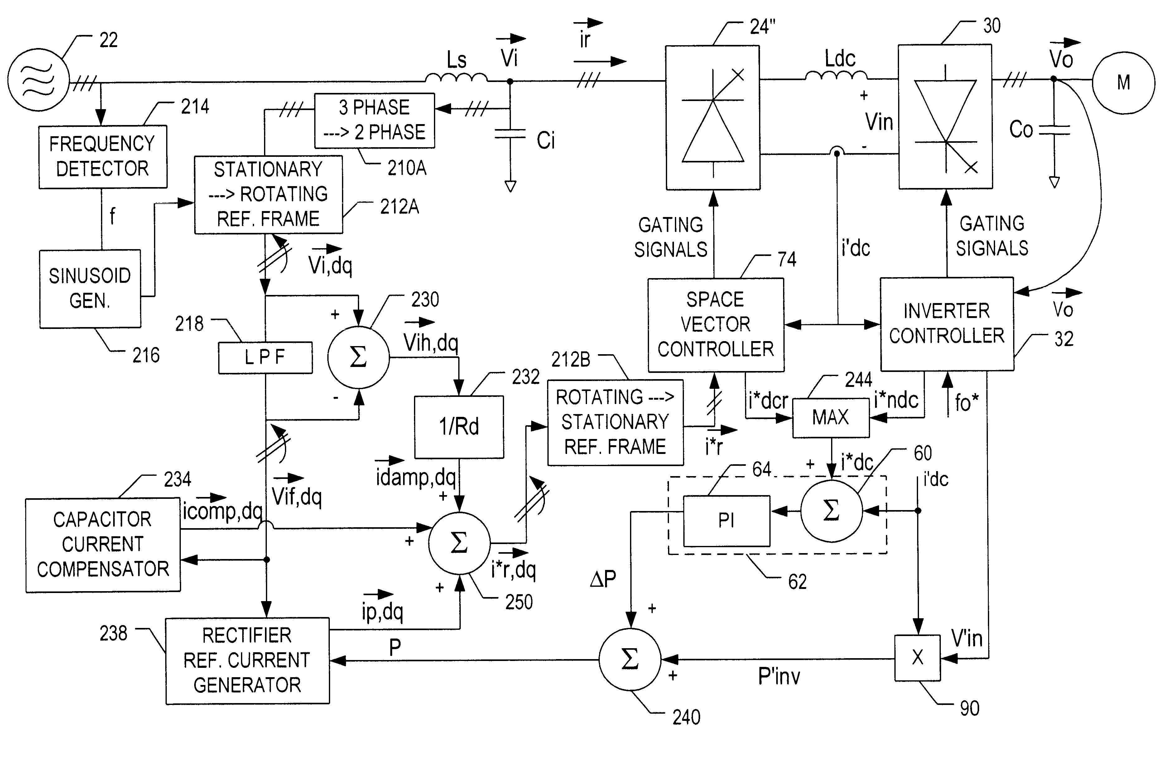
The detailed description is divided into three parts. The first portion of the discussion relates to active damping control in order to suppress resonance modes. The second part of the discussion centres on the enhancement of CSI-based drives through the use of feedforward control. These portions of the description are also described in co-pending U.S. application Ser. Nos. 09 / 515,289 and 09 / 516,974 and are repeated herein for convenience. The third part of the detailed description focuses on a PWM rectifier having de-coupled power factor and output current control loops and on the use of such a rectifier in an improved CSI-based drive such as discussed in the first two portions of this description.

1. Active Damping Control

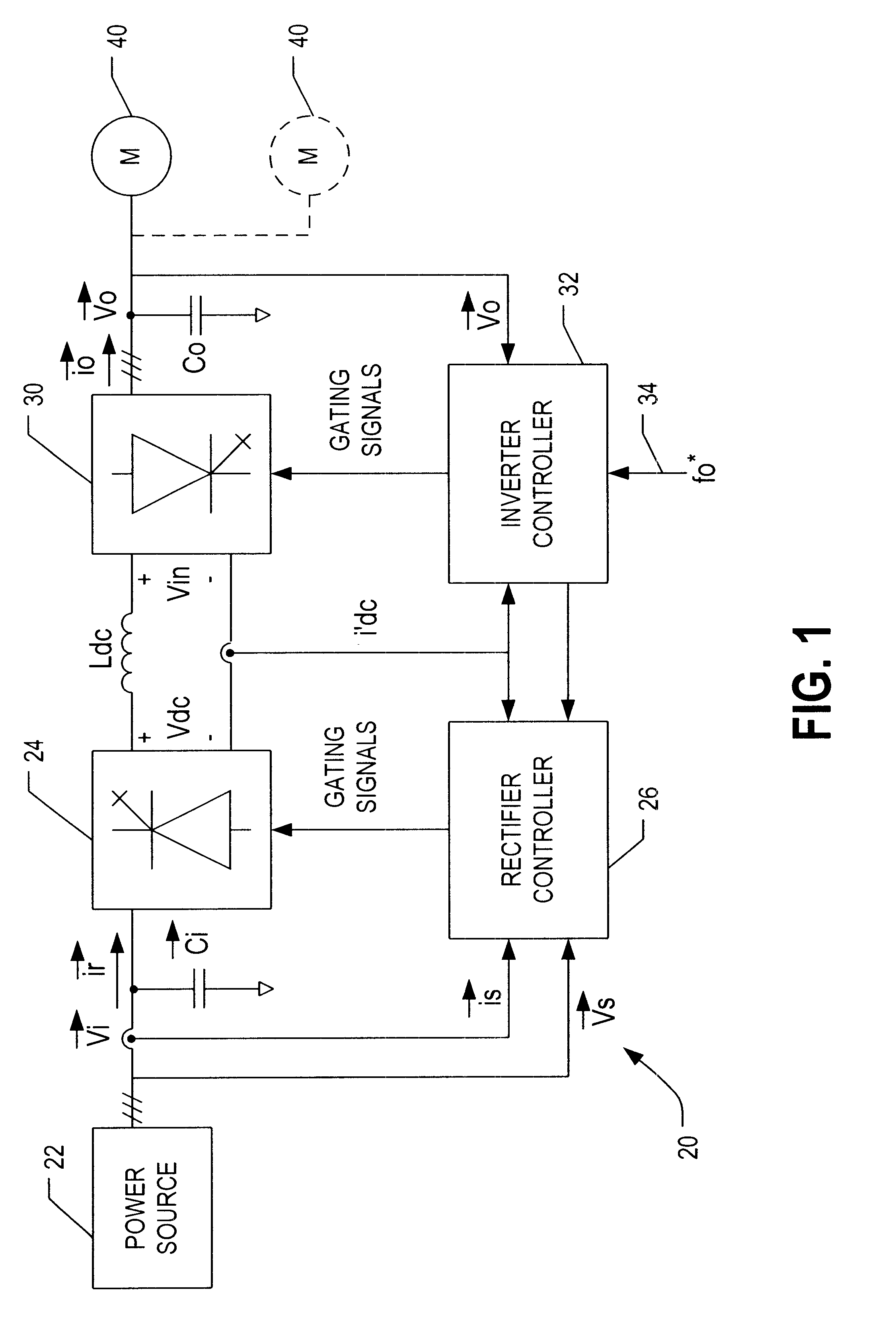
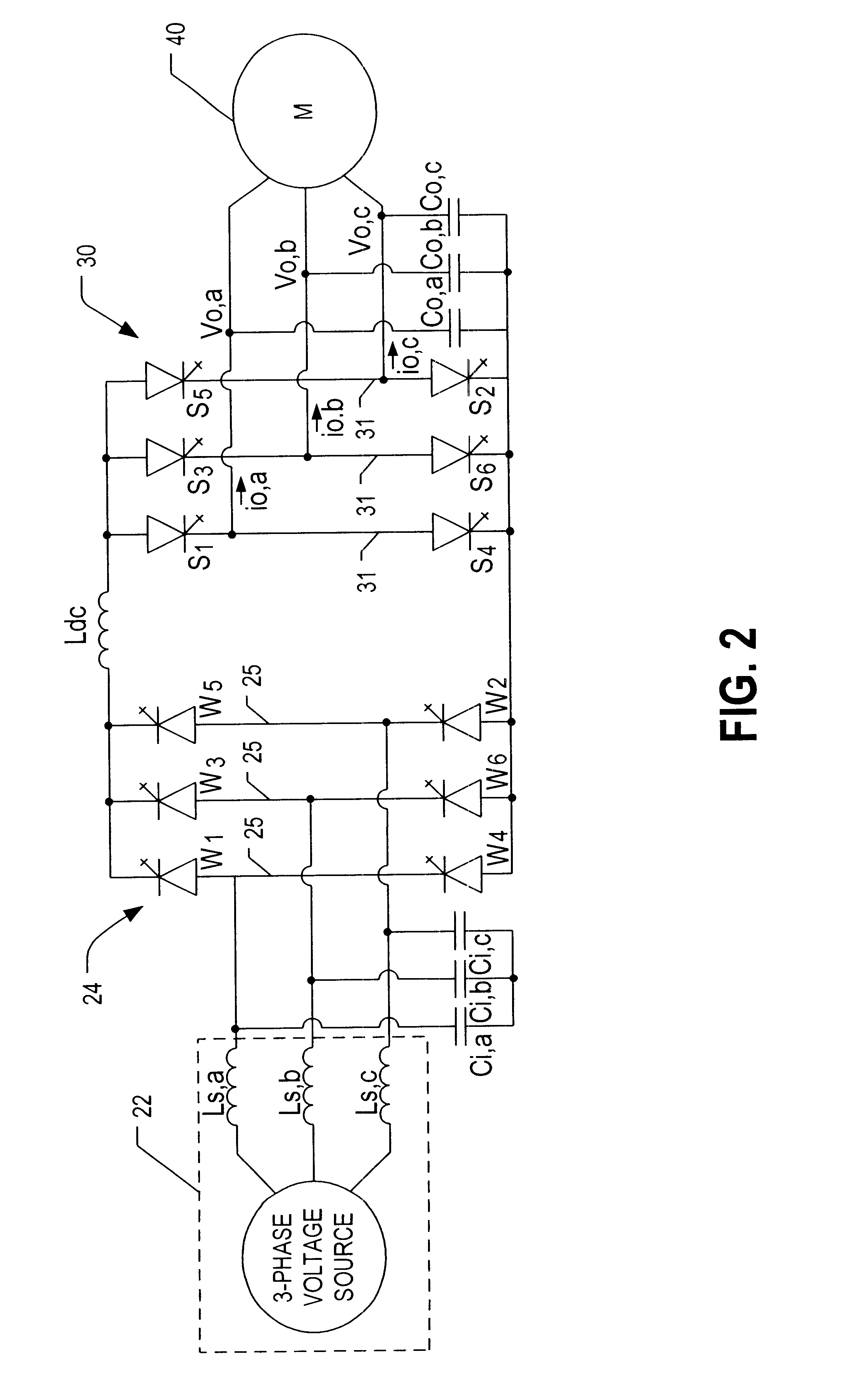
Referring to the drawings, FIG. 1 shows a schematic block diagram of a drive 20 for control of one or more a.c. induction motors 40. The drive 20 comprises a rectifier 24 coupled to a current source inverter 30 via a d.c. link choke or inductor L.sub.dc. The recti...


PUM


Abstract

A PWM rectifier wherein the switching bridge has m input filter capacitors, each connected at a terminal thereof, to the line side of the bridge. These terminals are used to connect an m-phase a.c. power supply (m>=1) having a per phase system inductance to the bridge. A current smoothing inductor is connected to the load side of the bridge and enables a load to be connected thereto. A switching pattern generator controls the switches in the switching bridge based on a reference output current. A first control loop is provided for determining an active portion of the reference output current based on a desired power level of the load and an m-phase voltage at the capacitor terminals. A second control loop is provided for determining a reactive portion of the reference output current based on the m-phase voltage at the capacitor terminals. The reactive portion of the current is selected so as to obtain a desired per phase power factor, such as unity, on the power supply. In this manner the output current and power factor control loops are independent of and not coupled to one another.

Description

The invention generally relates to the field of power electronics. More particularly, the invention relates to a pulse-width modulated (PWM) rectifier wherein the reactive and active powers are controlled independent of one another for improved performance. The PWM rectifier has particular utility in a current source inverter (CSI) based drive for controlling one or more high power alternating current (a.c.) induction motors.BACKGROUND OF INVENTIONCSI-based a.c. motor drives are increasingly used in high power (e.g., 1,000.about.10,000 hp) applications. See, for instance, P. M. Espelage and J. M. Nowak, "Symmetrical GTO Current Source Inverter for Wide Speed Range Control of 2300 to 4160 volt, 350 to 7000hp, Induction Motors", IEEE IAS Annual Meeting, pp 302-307, 1988. Compared with voltage source inverter fed drives, the CSI drive features simple structure, reliable short circuit protection, four quadrant operation capability and nearly sinusoidal output voltage and current wavefor...

Claims


Application Information

Patent Timeline
IPC IPC(8): H02M1/00H02M5/00H02M5/45H02M1/42
CPCH02M1/4216H02M5/4505Y02B70/126H02M2007/53876Y02B70/10Y02P80/10H02M7/53876
Inventor MA, DAMINGWU, BINZARGARI, NAVID R.RIZZO, STEVEN C.
Owner ROCKWELL AUTOMATION TECH
Why Eureka
Try Eureka