Methods and apparatus for reducing signal degradation

a signal degradation and signal technology, applied in the field of methods and apparatus for reducing signal degradation, can solve the problems of divergence, inability to work well with conventional coupling cancellation units, and inability to meet the requirements of a repeater transmission environment, and achieve the effect of minimizing the estimated error

Active Publication Date: 2002-04-04
WIPRO LTD
View PDF7 Cites 156 Cited by
  • Summary
  • Abstract
  • Description
  • Claims
  • Application Information

AI Technical Summary

Benefits of technology

0036] (iii) modifying said digital filter coefficients to minimize said estimated error.

Problems solved by technology

However, by contrast, in digital broadcasting, because of the scarceness of frequency resources, it is usually required that same signal is re-transmitted at the same frequency (i.e. over the same range of frequency) by all transmitters.
However, this assumption is not appropriate for a practical repeater transmission environment which generally has a multipath transmission channel (e.g. there are multiple radio paths between the master station and the relay station, each taking different times).
In a multipath channel, the distortion or attenuation of the master wave can be serious at a particular frequency (i.e. over a particular frequency range), especially when the amplitudes of the paths arriving at different time are the same.
In the presence of deep frequency selective fading caused by such multipath interference, the conventional coupling cancellation unit cannot work well and diverges, because the conventional coupling cancellation unit algorithm does not take the effect of multipath interference into account.
Furthermore, it is very difficult for a relay station to distinguish between multipath interference and coupling signals in the received signals.
Moreover, for non-coherent modulation, the conventional PSK (phase shift keying) estimation method cannot work well if there is a multipath channel.

Method used


Image

  • Methods and apparatus for reducing signal degradation
  • Methods and apparatus for reducing signal degradation
  • Methods and apparatus for reducing signal degradation

Examples


Embodiment Construction

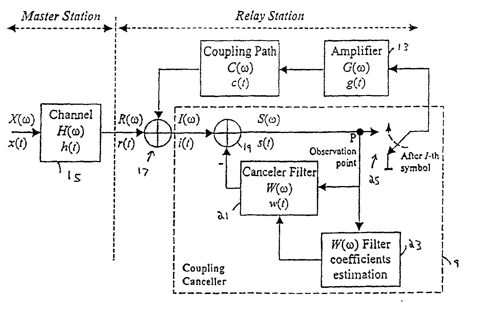
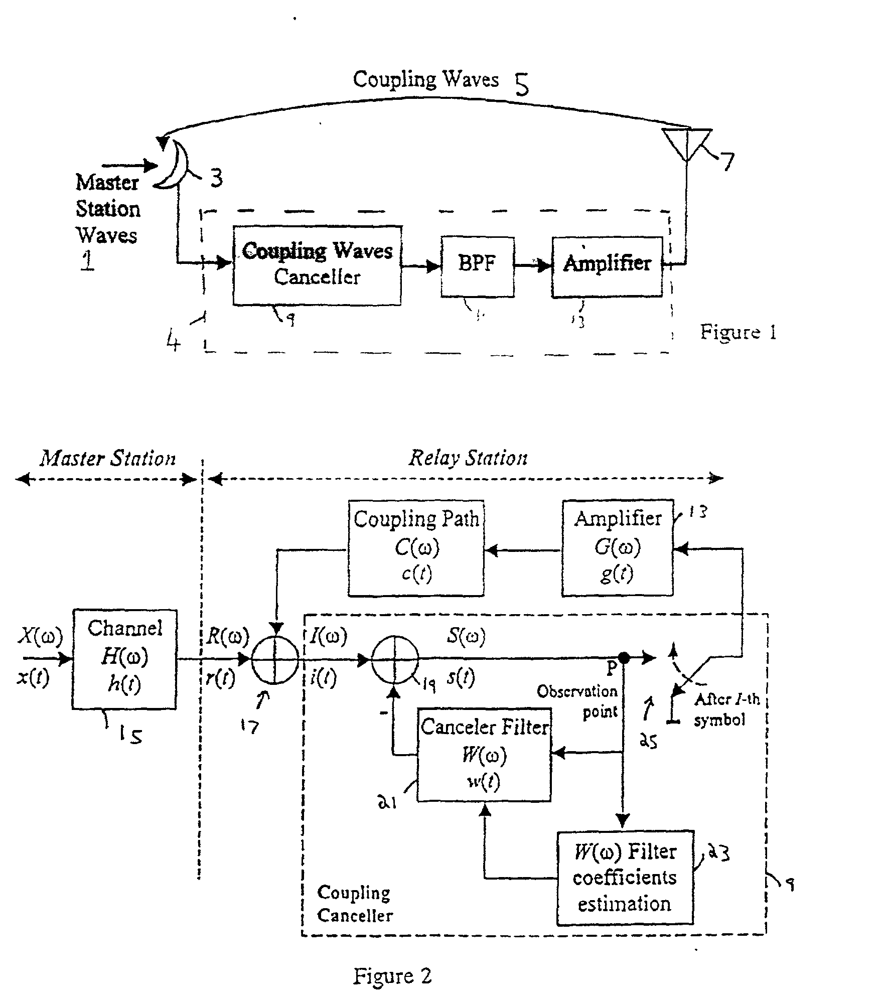
[0052] Like the conventional system discussed above, the present embodiment has the general structure illustrated in FIG. 1, but the coupling waves cancellation unit 9 is as illustrated in FIG. 2. The optional BPF 11 of FIG. 1 is omitted from FIG. 2 for simplicity. Likewise, FIG. 2 omits any A / D converter(s) in the system.

[0053] FIG. 2 shows the detail of the coupling wave cancellation unit and the principle of canceling coupling waves between the transmitting and receiving antennas of the broadcasting wave relay station. The master signal is x(t) (in the frequency domain X(.omega.)), which is subject to multipath interference h(t) (H(.omega.), in the frequency domain, is the multipath channel transfer function), in the channel 15 between the master station and the relay station, to produce a signal r(t) (R(.omega.) in the frequency domain).

[0054] The signal R((.omega.) from the master station is given by

R(.omega.)=X(.omega.).multidot.H(.omega.) (1)

[0055] A coupling wave is added to...


PUM


Abstract

A single frequency relay station receives a signal from a master station, and retransmits it. Before retransmitting the signal, the relay station uses a digital filter to subtract from the signal components which arise from multipath interference and coupling interference. The coefficients used by the digital filter are derived from characteristics of the multipath interference and the overall transfer function of the relay station. These are derived by turning off the retransmission, so that the multipath interference can be estimated from the received signal, and commencing the retransmission again, to determine the transfer function. A simplified inverse fast Fourier transform is used to simplify the calculations.

Description

[0001] The present invention relates to methods and devices for reducing noise in a signal received and re-transmitted by a relay station. The invention is particularly suitable if the signal received by the relay station includes multipath interference. The invention further relates to a relay station, such as a single frequency relay station.[0002] The ISDB-T (Integrated Services Digital Broadcasting--Terrestrial) BST-OFDM (band segmented transmission--orthogonal frequency division multiplexing) system is an example of what is often called a "single frequency network" (SFN).[0003] In fact, the signal is generally made up of multiple carrier signals. Each carrier has a finite, though narrow, frequency range, and when we talk about the frequency of a single carrier signal, we mean the center frequency of the narrow range. For multi-carrier transmission, such as OFDM in an ISDB-T system, each carrier has a different respective center frequency, and the frequencies are orthogonal to e...

Claims


Application Information

Patent Timeline
Patent Type & Authority Applications(United States)
IPC IPC(8): H03H21/00H04B7/155H04L25/03H04L27/26
CPCH03H21/0012H04L2025/03414H04L27/2647H04B7/15585
Inventor ZHU, JUNJIESUGIMOTO, HIROKIIKEDA, HIDETO
Owner WIPRO LTD
Why Eureka
Try Eureka