Displacement detection apparatus

a technology for displacement detection and equipment, applied in the direction of counting objects on conveyors, program control, instruments, etc., can solve the problems of difficult to precisely mark graduations on a single scale, difficult to prepare a single long scale and arrange it on a table, etc., to achieve long measurable range, minimize errors, and long measurable range

Active Publication Date: 2007-07-03
DMG MORI CO LTD
View PDF7 Cites 170 Cited by
  • Summary
  • Abstract
  • Description
  • Claims
  • Application Information

AI Technical Summary

Benefits of technology

[0020]In view of the above identified circumstances, it is desirable to provide a displacement detection apparatus that uses short scales and can provide a long measurable range comparable to a single long scale with a short head length.
[0021]Also, it is desirable to provide a displacement detection apparatus that is not apt to be influenced by signal distortions and provides a long measurable range by means of a single scale, while minimizing the error that can arise at the time of switching.
[0022]Thus, while a displacement detection apparatus according to the invention uses short scales, it can provide a measurable length substantially equal to that of a conventional displacement detection apparatus that uses a long scale and hence it can use a short bed. In other words, the scales are lightweight and can be manufactured at low cost. Additionally, the scales are less liable to be stained by dirt and dust if compared with a long scale because they are short so that the reliability of the apparatus will be improved. It is easy to handle the scales so that the short scale is easily fitted to a table. Further, it is easy to manufacture the scales. The bed length can be shortened so that a machine tool and the like to which the displacement detection apparatus is fitted can be downsized.
[0023]Still additionally, a displacement detection apparatus according to the invention is less affected by distorted signals because it is adapted to detect a differential value within a wavelength of a scale signal by using a same high speed clock. Furthermore, switching errors can be reduced when an external switching signal is used.

Problems solved by technology

Meanwhile, it is difficult to prepare the scale of a displacement detection apparatus having a single scale and a single head section as illustrated in FIGS. 1A through 1D because of the large length of the scale.
Therefore, in the case of a long scale, it is difficult to precisely mark graduations on a single scale.
This means that it is difficult to prepare a single long scale and arrange it on a table.
This means that, if the displacement detection apparatus is fitted to a machine tool, the latter is forced to have large dimensions.
In other words, it has not been possible to arrange a single scale and a plurality of heads.
Therefore, it is not possible to shorten the cycle of sampling the differential value.
Therefore, it is not possible to realize a high resolution unless a very high clock frequency is used.
While a very high clock frequency is required, it is not possible for a magnetic scale apparatus to realize such a high clock frequency.
The impossibility of raising the clock frequency of clocks that come into a phase shift means the impossibility of reducing the cycle of sampling the amplitude of the phase shift.
However, in reality, there is a disparity of graduation errors as illustrated in FIG. 4A.
Then, such a magnetic scale apparatus poorly provides reproducibility and can highly probably entail errors.

Method used


Image

  • Displacement detection apparatus
  • Displacement detection apparatus
  • Displacement detection apparatus

Examples


first embodiment

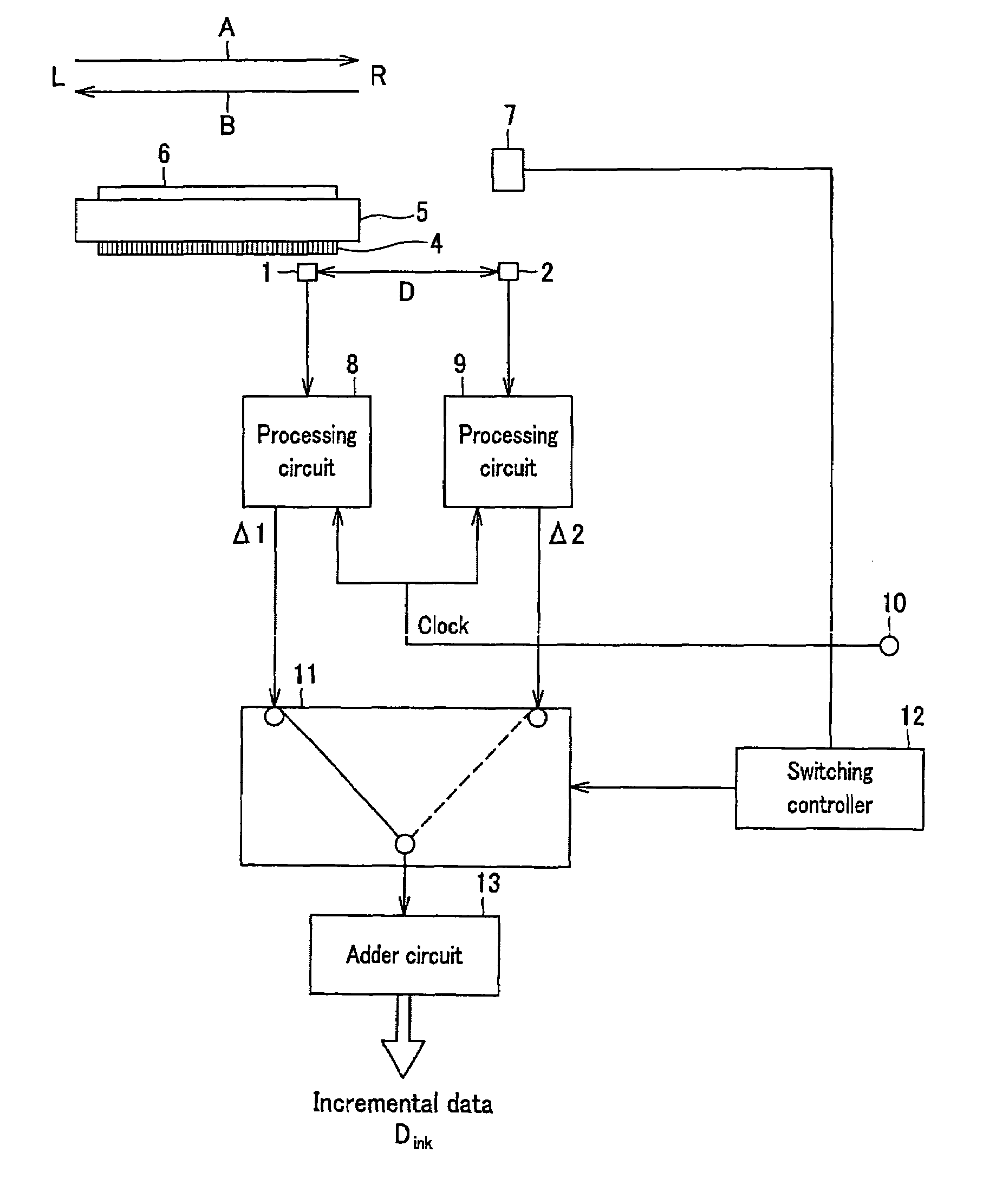
[0057]FIGS. 7A through 7C are schematic illustrations of the relative positions of the scale 4 and the heads 1 and 2 of the More specifically, FIG. 7A shows the left limit of the scale 4 and FIG. 7C shows the right limit of the scale 4. FIG. 7B shows a position of the scale 4 in which both the signal from the head 1 and the signal from the head 2 are effective. It will be appreciated that FIGS. 7A, 7B and 7C are respectively simplified versions of FIGS. 6A, 6B and 6C.

[0058]The gap separating the head 1 and the head 2 is made smaller than the length L of the scale 4 so that the differential value Δ1 and the differential value Δ2, which will be described in greater detail hereinafter, may be switched from one to the other in a situation as illustrated in FIG. 7B. Since the head 1 and the head 2 are displaceable relative to the scale 4, it is possible to detect periodic analog signals of a plurality of different types as a function of the graduations cut on the scale 4 at a predetermi...

second embodiment

[0123]FIG. 24 is a schematic illustration of the relative positions of the single scale 24 and the three heads 21, 22 and 23 of FIG. 22. Since the differential value Δ1, the differential value Δ2 and the differential value Δ3, which will be described in greater detail hereinafter, are selectively used, the two gaps separating any two adjacent ones of the three heads 21, 22 and 23 (the gap D1 between the head 21 and the head 22 and the gap D2 between the head 22 and the head 23) are made shorter than the length of the scale 24. Since the head 21, the head 22 and the head 23 are displaceable relative to the scale 24, it is possible to detect periodic analog signals of a plurality of different types as a function of the graduations cut on the scale 24 at a predetermined pitch. As pointed out earlier, a periodic analog signal as used herein may refer to a sine wave sin or a cosine wave cos. Alternatively, it may be a plurality of sine waves sin or cosine waves cos. Optical heads are use...

third embodiment

[0157]Now, the operation of the third embodiment will be described in greater detail below. FIG. 26B illustrates a state where both the head 31 and the head 32 output periodic analog signals respectively to the processing circuit 8 and the processing circuit 9. At this time, the processing circuit 8 and the processing circuit 9 respectively output the differential data Δ1 and the differential data Δ2 to the changeover switch 11.

[0158]As described above, the scale position detector 41 supplies “H” to the switching controller 12 when light emitted from the light emitting side is received by the light receiving side without being blocked by any of the light shield plates 38, 39 and 40 but supplies “L” to the switching controller 12 when light emitted from the light emitting side is blocked. Therefore, for example, when the scale 33 is moved in the direction of arrow B from the state as illustrated in FIG. 23A to the state as illustrated in FIG. 26B, the scale position detector 41 outpu...


PUM


Abstract

The present invention provides a displacement detection apparatus uses short scales and can provide a long measurable range comparable to a single long scale with a short bed length. The displacement detection apparatus includes a scale, a first head and a second head adapted to detect periodic analog signals of a plurality of different types, a first processing section and a second processing section that detects the first differential value and the second differential value between the immediately preceding positional data and the current positional data obtained by sampling the periodic analog signals of a plurality of different types, a switching section that selectively switches from the first differential value to the second differential value or vice versa, a scale position detection section that detects the scale getting to a predetermined position relative to the first head or a predetermined position relative to the second head, a switching control section that causes the switching section to switch from either of the differential values to the other in response to the detection of the scale getting to the predetermined position, and an addition section that adds the first differential value or the second differential value selectively switched by the switching control section and outputting it as positional information.

Description

CROSS REFERENCE TO RELATED APPLICATIONS[0001]The present invention contains subject matter related to Japanese Patent Application JP 2004-127205 filed in the Japanese Patent Office on Apr. 22, 2004, the entire contents of which being incorporated herein by reference.BACKGROUND OF THE INVENTION[0002]1. Field of the Invention[0003]This invention relates to a displacement detection apparatus for detecting the relative position of a moving apparatus, which may be a machine tool, an inspection apparatus or a semiconductor manufacturing system.[0004]2. Description of the Related Art[0005]Displacement detection apparatus for detecting the relative position of a moving apparatus, which may be a machine tool or a semiconductor manufacturing system, are known. Such a displacement detection apparatus comprises a scale on which a periodic signal having a constant wavelength is recorded in a predetermined direction with a fluctuating signal level, a head section for detecting the periodic signal...

Claims


Application Information

Patent Timeline
Patent Type & Authority Patents(United States)
IPC IPC(8): G01D5/245G01D5/244G01D5/249G01D5/26G01D5/36G05B19/402G06M7/00
CPCG03F7/70775G05B19/402G05B2219/45031G05B2219/37112G01D5/34746G01B7/00G01D5/245
Inventor NABESHIMA, NOBUOTANIGUCHI, KAYOKOKANBARA, EIKO
Owner DMG MORI CO LTD
Why Eureka
Try Eureka