
Battery configuration for an electric vehicle

a battery configuration and electric vehicle technology, applied in the field of electric vehicles, can solve the problems of industrial air scrubbers, too large, expensive or expensive to install on board individual vehicles, and the pollution level in emerging commercial centers becomes increasingly unmanageabl

Active Publication Date: 2014-04-24
GOGORO
View PDF19 Cites 52 Cited by
  • Summary
  • Abstract
  • Description
  • Claims
  • Application Information

AI Technical Summary

Benefits of technology

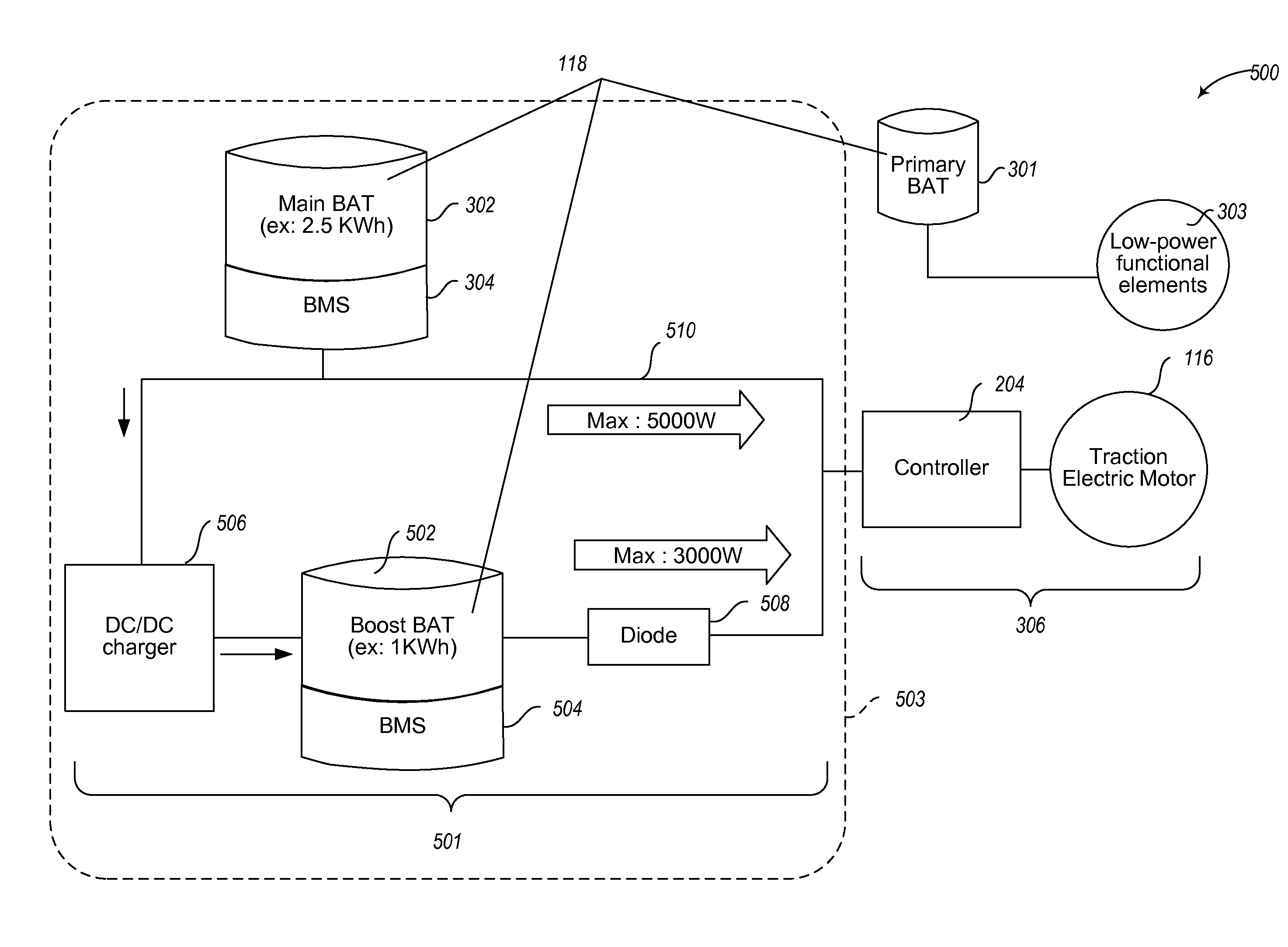
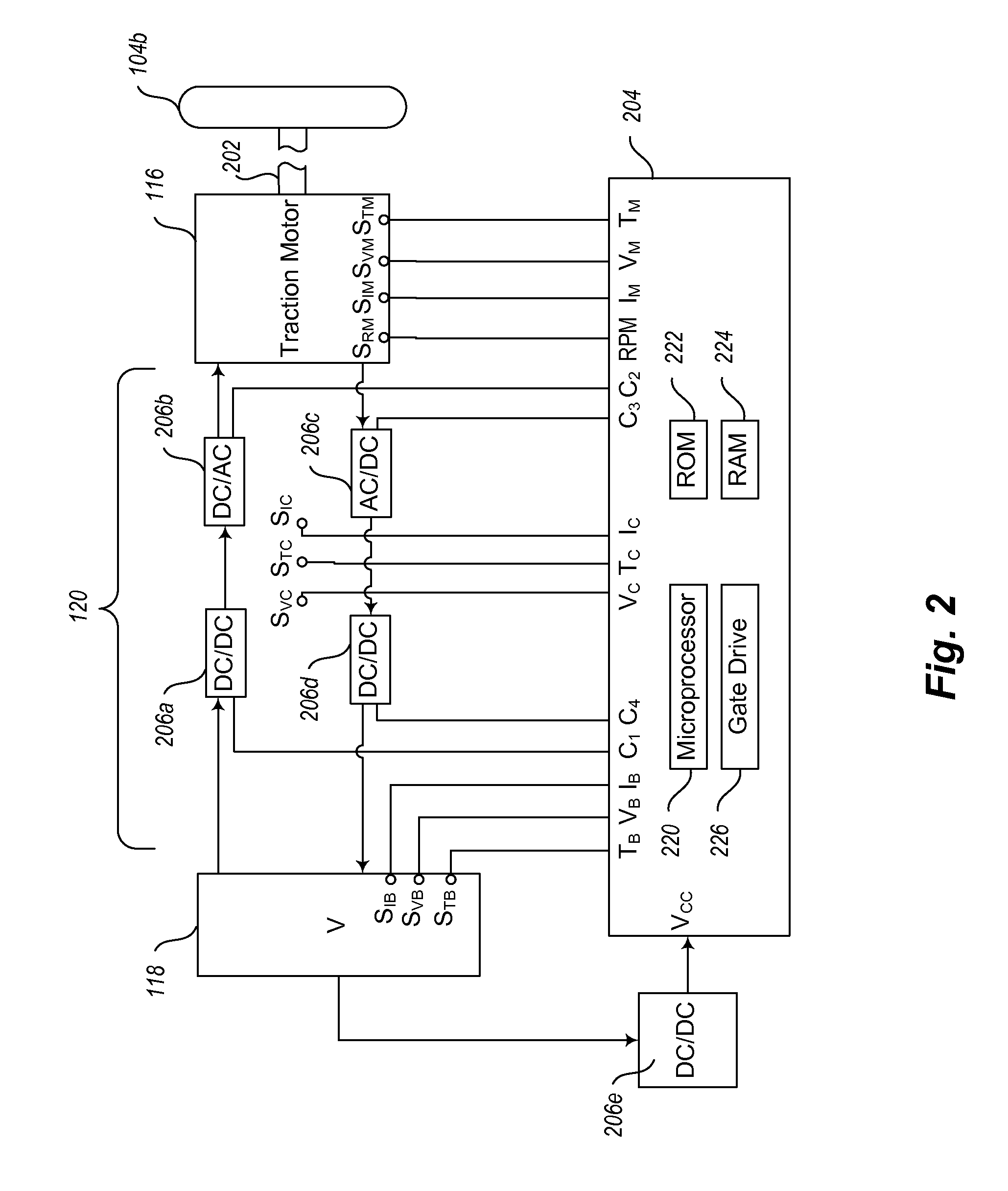
The power delivery system for an electric vehicle described in this patent allows for a long driving range and efficient power management for both continuous and intermittent high-performance operation. It uses an auxiliary boost stage and an on-board charging circuit to provide power to the electric motor. The system also includes a main battery and a boost battery that can work together to power the vehicle at a high power discharge rate. The charging circuit ensures that the main and boost batteries can cooperate even if they have different chemistries. This system is particularly useful for personal transport vehicles such as scooters or motorbikes. The patent describes an embodiment where the boost battery can automatically participate in powering the electric motor based on sensed changes in the load. The power management can also be based on timed intervals.

Problems solved by technology

The need for emission reduction becomes greater as more people throughout the world acquire engine-powered vehicles, and as pollution levels in emerging commercial centers become increasingly unmanageable.
Also for example, electricity may be generated at plants that burn relatively clean burning fuels (e.g., natural gas), which have higher efficiency than internal combustion engines, and / or which employ pollution control or removal systems (e.g., industrial air scrubbers) which are too large, costly or expensive to install on board individual vehicles.
One barrier to adoption of electric motors for vehicles is that electric motors tend to be under-powered compared to their gasoline engine counterparts.
Consequences of engine power constraints for electric vehicles in particular include limiting their range before charging is necessary, and hampering their usefulness in hilly areas or in off-road conditions.

Method used


Image

  • Battery configuration for an electric vehicle
  • Battery configuration for an electric vehicle
  • Battery configuration for an electric vehicle

Examples


Embodiment Construction

[0019]It will be appreciated that, although specific embodiments of the present disclosure are described herein for purposes of illustration, various modifications may be made without departing from the spirit and scope of the present disclosure. Accordingly, the present disclosure is not limited except as by the appended claims.

[0020]In the following description, certain specific details are set forth in order to provide a thorough understanding of various aspects of the disclosed subject matter. However, the disclosed subject matter may be practiced without these specific details. In some instances, well-known structures and methods of power delivery comprising embodiments of the subject matter disclosed herein have not been described in detail to avoid obscuring the descriptions of other aspects of the present disclosure.

[0021]Unless the context requires otherwise, throughout the specification and claims that follow, the word “comprise” and variations thereof, such as “comprises”...


PUM


Abstract

A power delivery system for an electric vehicle provides efficient power management for either continuous or intermittent high-performance operation, using a boost stage and an on-board charging circuit. A main battery, configured as a high-capacity power source, supplies power to the electric motor under normal load conditions. An auxiliary boost battery assists the main battery in supplying a high-level current at a higher discharge rate thereby causing the motor to operate in a high-performance drive mode. A charging circuit recharges the boost battery from the main battery during operation of the motor. The charging circuit also maintains a charge balance between the boost battery and the main battery when the two batteries have different chemistries. In one embodiment, participation of the boost battery in powering the electric motor can be controlled automatically according to sensed changes in the load. In another embodiment, power management can be based on timed intervals.

Description

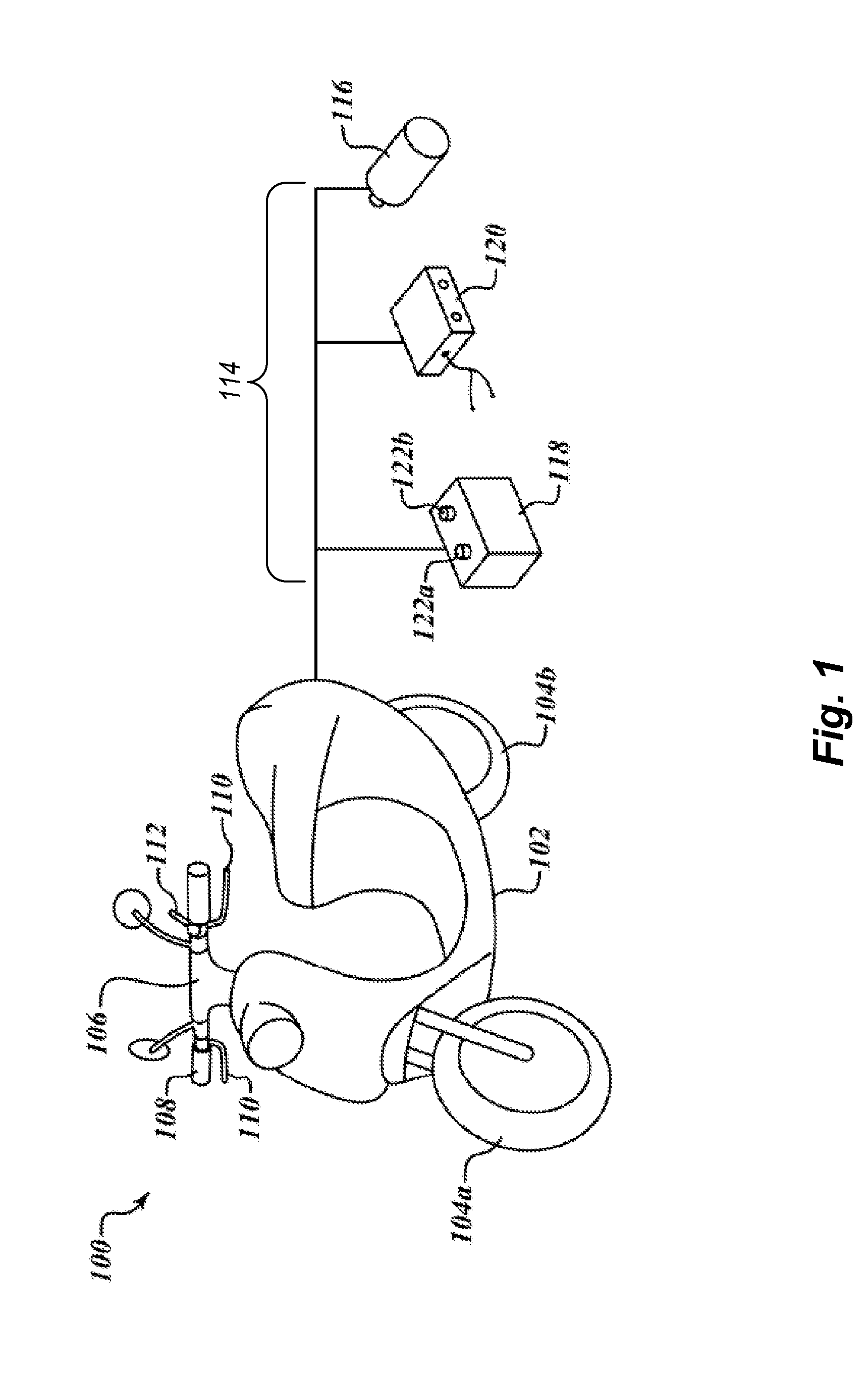
CROSS-REFERENCE TO RELATED APPLICATION[0001]This application claims benefit of U.S. Provisional Patent Application No. 61 / 716,388 filed on Oct. 19, 2012, which is hereby incorporated by reference in its entirety.BACKGROUND[0002]1. Technical Field[0003]The subject matter described herein generally relates to vehicles that employ electric motors and, in particular, multiple-battery configurations used to supply power to such vehicles.[0004]2. Description of the Related Art[0005]It is generally agreed that reducing toxic emissions on a global scale will require alternatives to gasoline-powered and diesel-powered internal combustion engines currently used in vehicles, especially in automobiles and trucks. The need for emission reduction becomes greater as more people throughout the world acquire engine-powered vehicles, and as pollution levels in emerging commercial centers become increasingly unmanageable.[0006]One viable solution is to encourage the use of electric personal transport ...

Claims


Application Information

Patent Timeline
Patent Type & Authority Applications(United States)
IPC IPC(8): B60L11/18
CPCB60L11/1809B60L15/20B60L15/2009B60L2200/12B60L2200/22B60L2200/36B60L2200/40B60L2210/12B60L2210/14B60L2240/12B60L2240/421B60L2240/423B60L2240/425B60L2240/545B60L2240/547B60L2240/549B60L2250/10B60L15/209B60L15/30B60L50/40B60L50/51B60L53/80B60L58/12B60L58/22B60L58/20Y02T10/64Y02T10/70Y02T10/72Y02T10/7072
Inventor WU, YI-TSUNG
Owner GOGORO
Learn More