
Fuse unit

a technology of fuse unit and fuse body, which is applied in the direction of relays, electrical equipment, emergency protective devices, etc., can solve the problems of inability to energize a fusible body, inability to largely take sectional area, and inability to thicken the thickness of plates

Active Publication Date: 2015-05-14
YAZAKI CORP
View PDF10 Cites 12 Cited by
  • Summary
  • Abstract
  • Description
  • Claims
  • Application Information

AI Technical Summary

Benefits of technology

The present invention aims to provide a fuse unit that can easily incorporate the desired fusible body with commensurate resistance value into the circuit body and remove it after it has fused. This should reduce the labor and manufacturing time required for incorporating the fuse into a circuit.

Problems solved by technology

In addition, in a case where the circuit body and the fusible body are integrally formed, since it results in a fuse capacity of the same plate thickness as the plate thickness of the circuit body, that is, the same sectional area, the plate thickness cannot be thickened, that is, the sectional area cannot be largely taken in order to energize a fusible body for large current.

Method used


Image

  • Fuse unit
  • Fuse unit
  • Fuse unit

Examples


Embodiment Construction

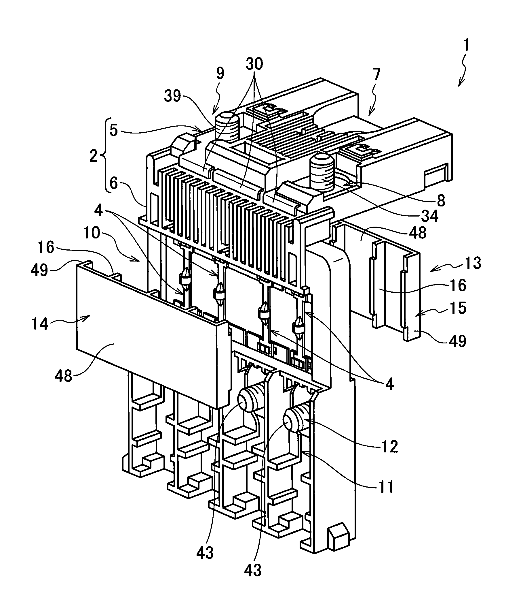
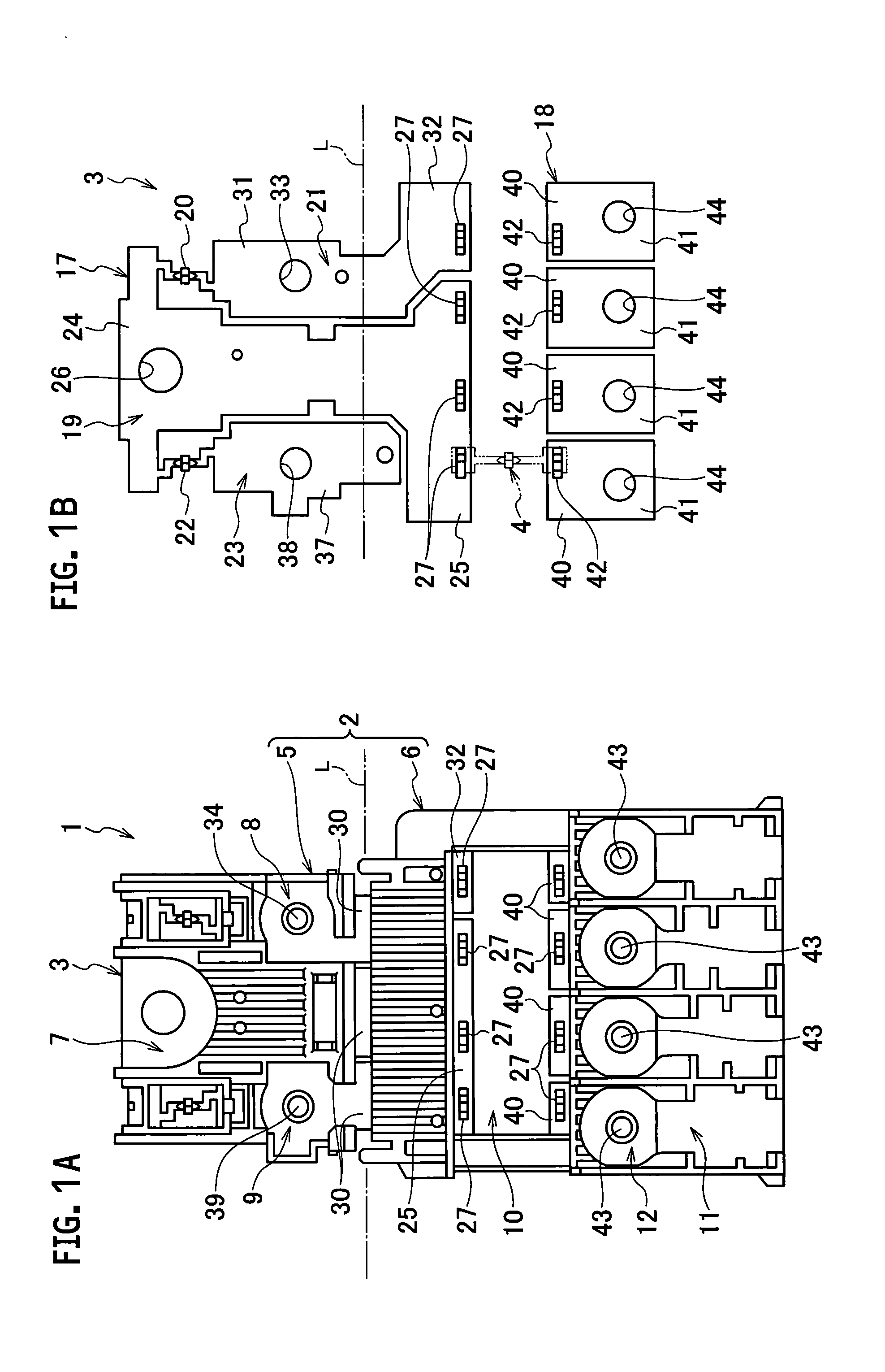
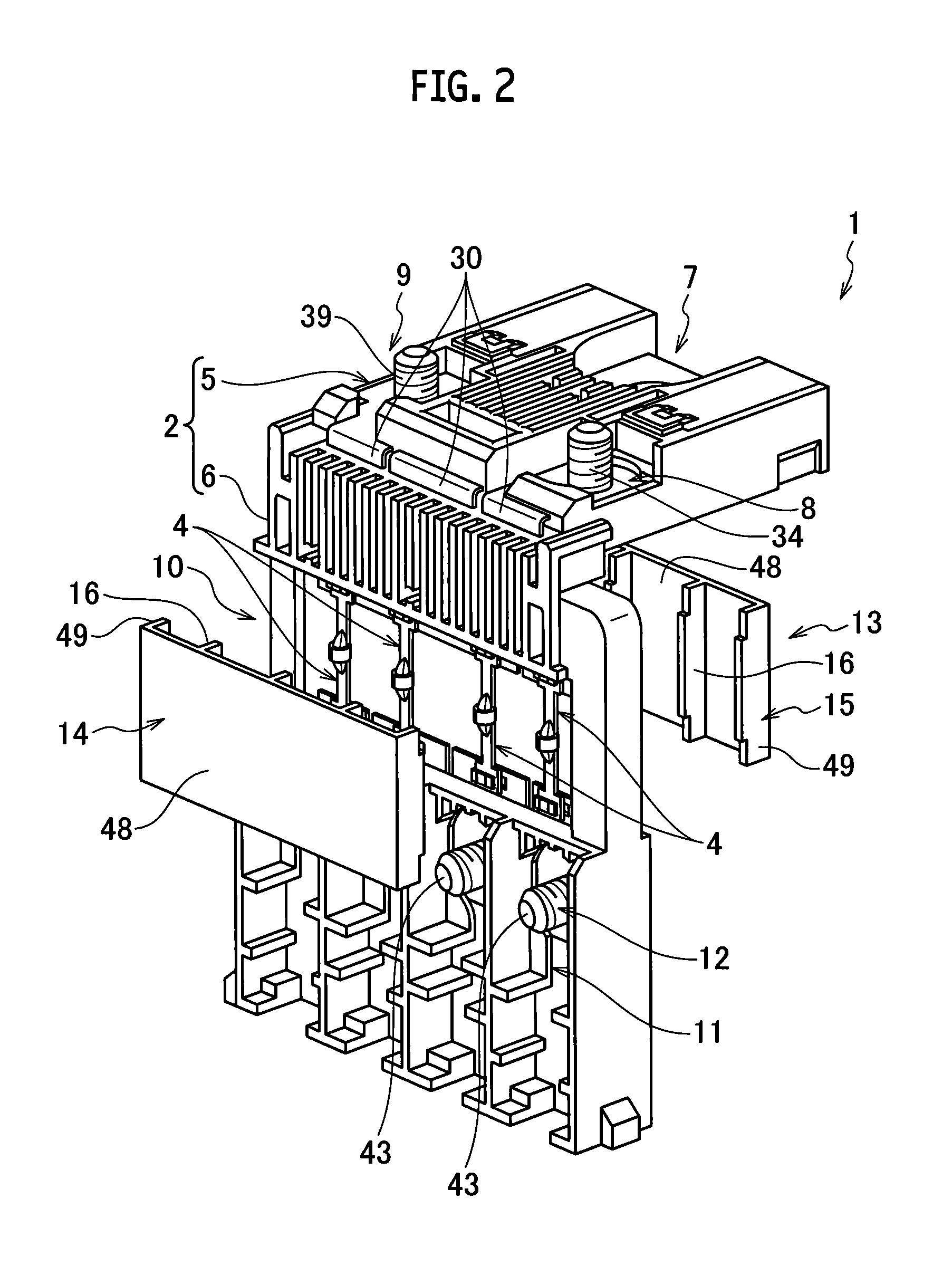
[0024]In the following, embodiments of the present invention will be described on the basis of the drawings. As shown in FIG. 1A, FIG. 1B and FIG. 2, a fuse unit 1 of the present embodiment is provided with a resin housing 2 formed by an insulator, a circuit body 3 that is formed by a conductor, is molded integrally with the resin housing 2 and branches and transfers electric power from a power source side to a load side, and a fusible body 4 that is provided on this circuit body 3 and fuses at overcurrent to the load side. In addition, the circuit body 3 is formed by a block side circuit body 17 to be connected to the power source side, and a block side terminal body 18 to be connected to the load side, block side first connection end 25, 32 to which fusible body side first connection ends 45 of the fusible bodies 4 are to be detachably connected are formed on the block side circuit body 17, and a block side second connection end 40 to which a fusible body side second connection en...


PUM


Abstract

A fuse unit comprising a resin housing formed by insulator, a circuit body formed by conductor, molded integrally with the resin housing and branching and transferring electricity from a power source side to a load side, and a fusible body provided on the circuit body and fusing at overcurrent to the load side; the circuit body is formed by a block side circuit body connected to the power source side, and a block side terminal body connected to the load side, a block side first connection end to which one side of the fusible body is detachably connected is formed on the block side circuit body, and a block side second connection end to which the other side of the fusible body is detachably connected is formed on the block side terminal body.

Description

CROSS REFERENCE TO RELATED APPLICATIONS[0001]This application is a Continuation of PCT Application No. PCT / JP2013 / 068223, filed on Jul. 3, 2013, and claims the priority of Japanese Patent Application No. 2012-162354, filed on Jul. 23, 2012, the content of both of which is incorporated herein by reference.TECHNICAL FIELD[0002]The present invention relates to a fuse unit in which a fuse is incorporated into a conductive circuit body formed integrally with an insulating resin housing.BACKGROUND ART[0003]A fuse unit is proposed in which a conductive circuit body that has a bus bar with which a fuse element (fusible body) is integrally formed is molded integrally with an insulating resin housing, and the circuit body and the fusible body are embedded in the resin housing. Since, in this fuse unit, the fusible body is formed integrally with the circuit body, labor of connecting the fusible body to the circuit body is saved and assemblability is improved.[0004]However, in the fuse unit in ...

Claims


Application Information

Patent Timeline
Patent Type & Authority Applications(United States)
IPC IPC(8): H01H45/02H01H61/04
CPCH01H61/04H01H45/02H01H85/044H01H85/12H01H85/143H01H85/153H01H2085/025H01H2085/0555
Inventor TOTSUKA, MITSUHIKOMASUDA, TOSHIKO
Owner YAZAKI CORP
Learn More