Elevator backup power supply

a technology for power supply and electric lifter, applied in the direction of emergency power supply arrangement, electric lifter, electrical apparatus, etc., can solve the problems of reducing reliability and running on batteries

Active Publication Date: 2015-05-21
OTIS ELEVATOR CO
View PDF16 Cites 17 Cited by
  • Summary
  • Abstract
  • Description
  • Claims
  • Application Information

AI Technical Summary

Problems solved by technology

Alternatively, the controller may be reconfigured or replaced so as to run off of the DC battery at all times. Running on the batteries at all times may be problemat

Method used


Image

  • Elevator backup power supply
  • Elevator backup power supply
  • Elevator backup power supply

Examples


Embodiment Construction

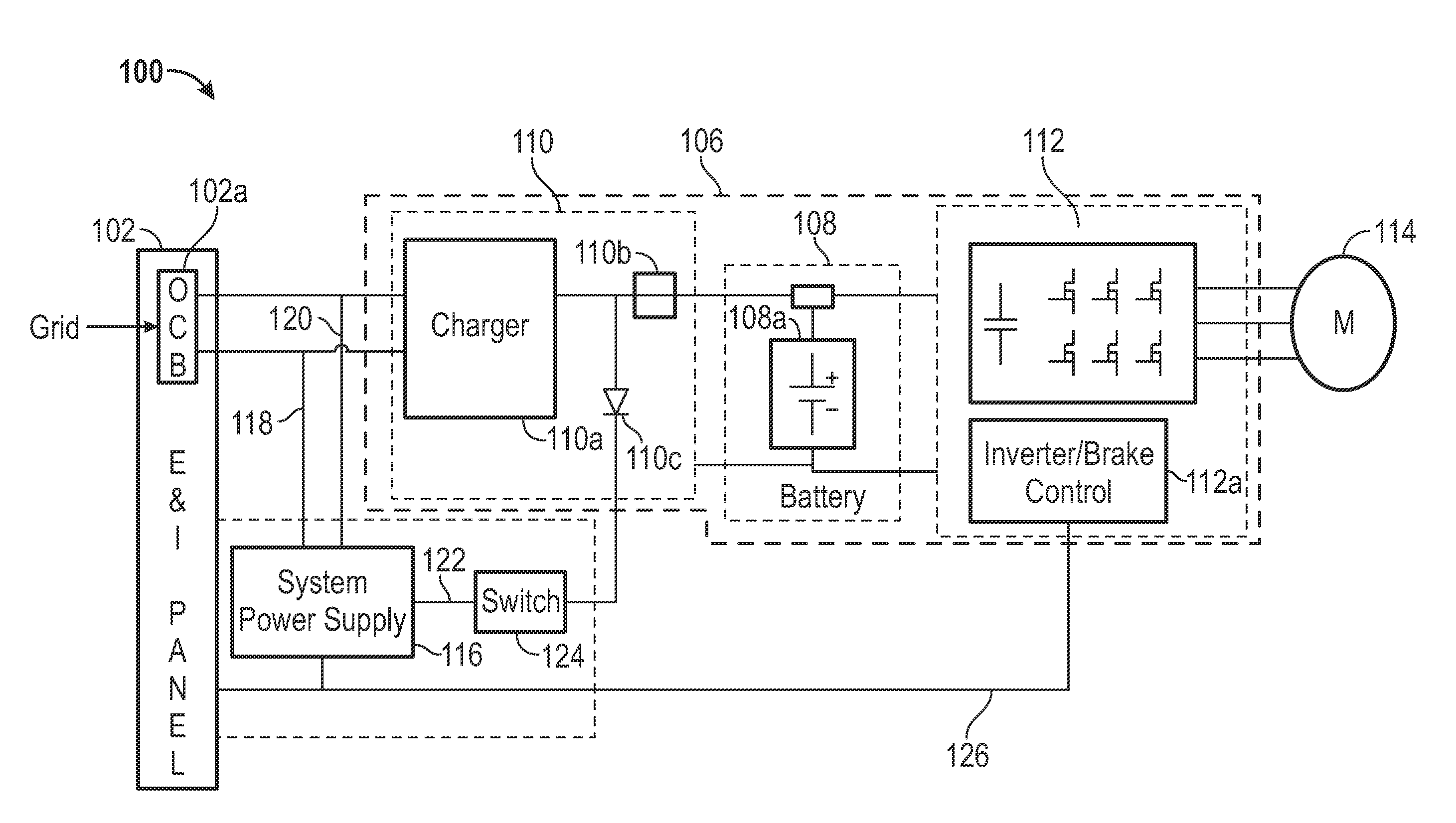
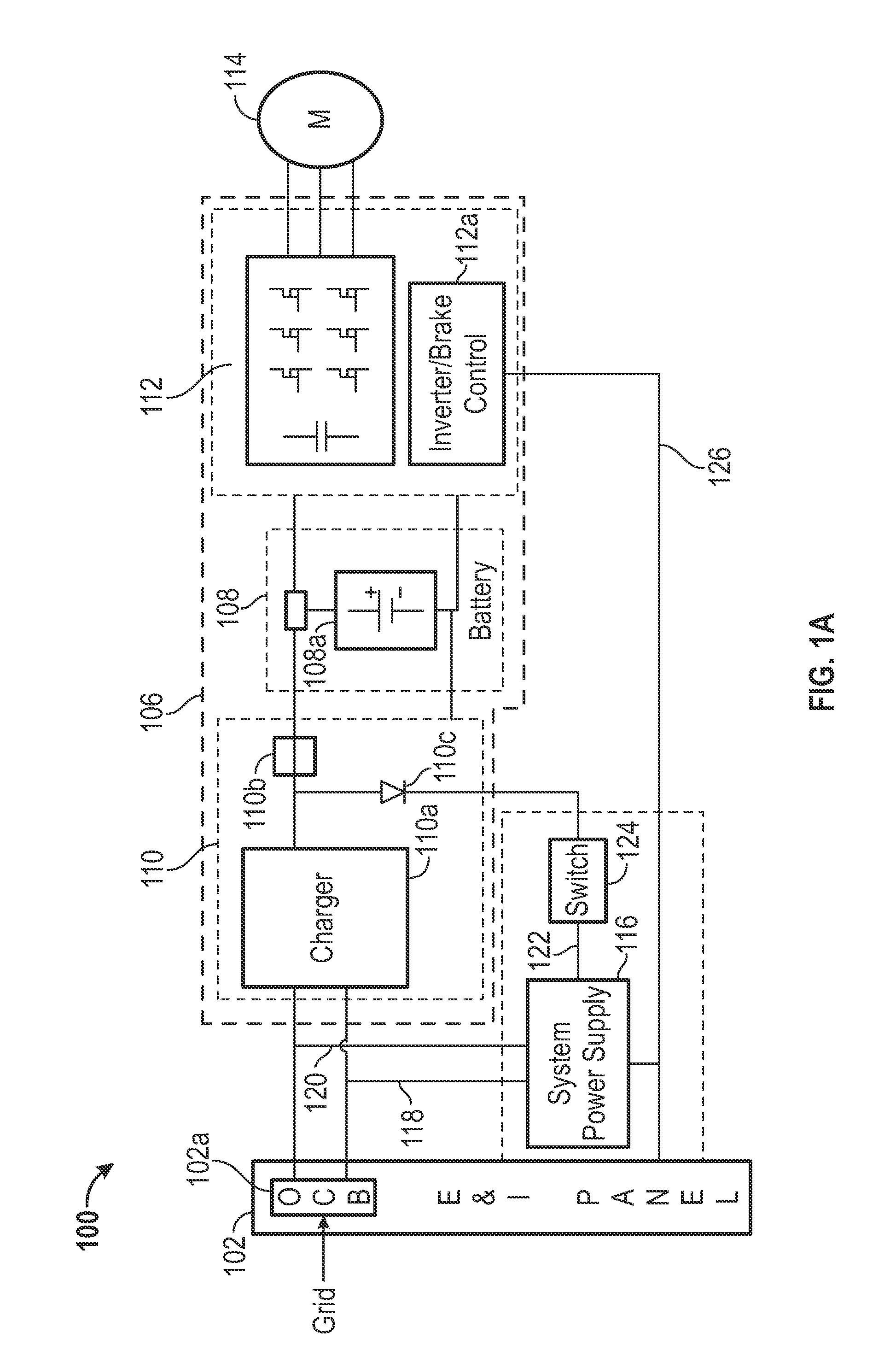
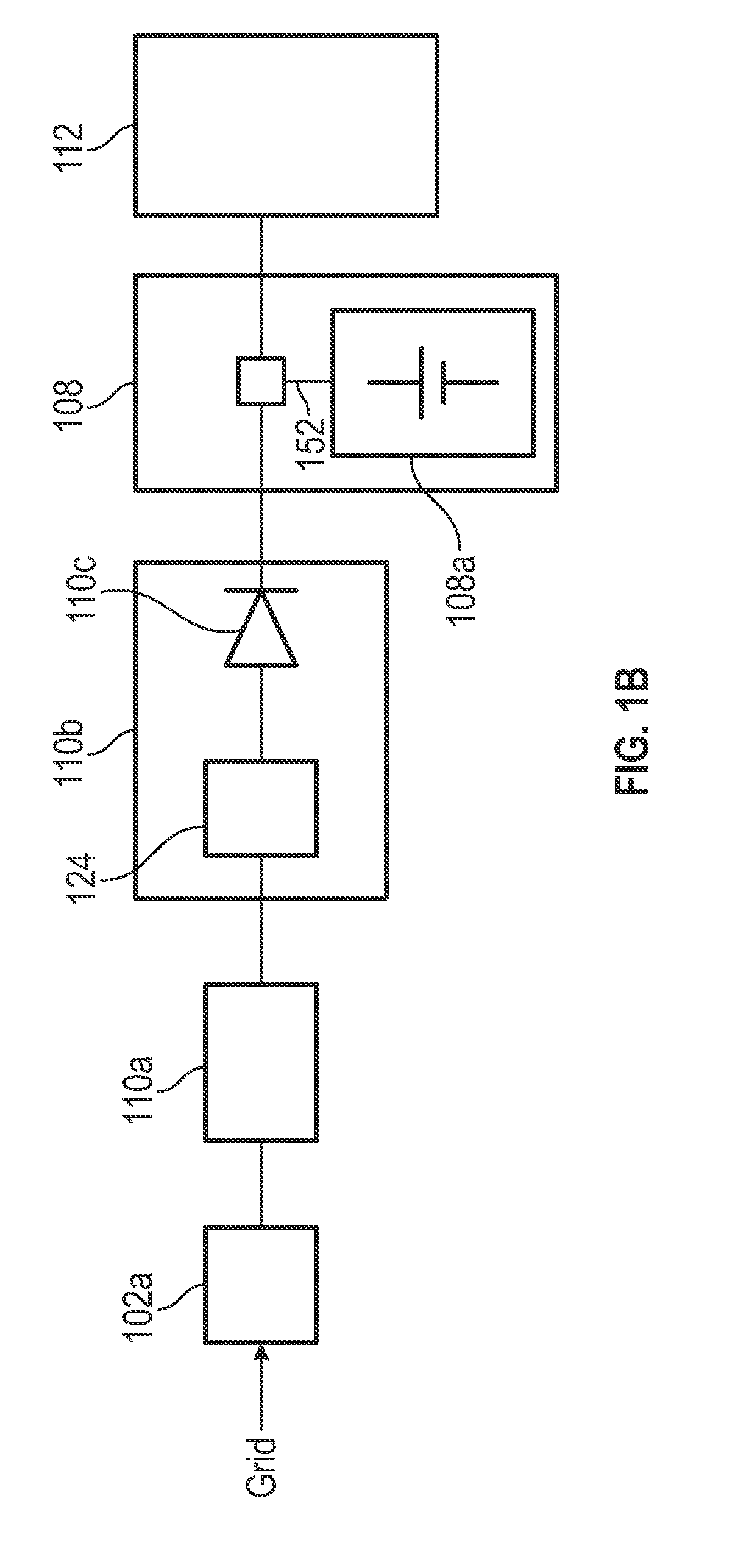
[0011]Exemplary embodiments of apparatuses, systems and methods are described for safely and effectively distributing power. In some embodiments, power to, e.g., an elevator may be provided from one or more sources. The one or more sources may include a grid and a battery. Embodiments may be used to selectively connect or disconnect power to an elevator. A select coupling of power may help to ensure safety of personnel when, e.g., servicing, maintaining, or repairing the elevator.

[0012]In some embodiments, efficient and cost effective solutions may be provided for interfacing a controller to a battery. In some embodiments, the controller might not be entirely reliant on the battery and might not need a DC / AC converter to be powered from the battery. In some embodiments, reliability may be improved or enhanced by avoiding a single point failure at the battery.

[0013]It is noted that various connections are set forth between elements in the following description and in the drawings (th...


PUM


Abstract

A power architecture for an elevator system is described. The power architecture may comprise a panel receiving power from a power grid through a breaker, a power supply coupled to the breaker to receive power from the grid, a battery coupled to the power supply through a switch, an elevator motor controller coupled to the power supply, the power supply providing power from at least one of the grid and the battery to the controller, and a charger coupled to the breaker and the battery and configured to receive power from the power grid and provide power to the battery to charge the battery.

Description

BACKGROUND[0001]Batteries are becoming increasingly prevalent in systems, such as elevator systems. One reason a battery may be implemented in an elevator system is to provide backup power for rescue functions in the event of a power loss in the system.[0002]Batteries used in elevator applications may provide direct current (DC) voltages. Many elevator controllers, however, are designed to receive alternating current (AC) voltages. In order to interface a DC battery to an AC controller, a DC-to-AC (DC / AC) converter may be used. Alternatively, the controller may be reconfigured or replaced so as to run off of the DC battery at all times. Running on the batteries at all times may be problematic, because it may require a second energy conversion to power the controller, and it creates a single point of failure at the battery, thereby reducing reliability.BRIEF SUMMARY[0003]An embodiment of the disclosure is directed to a power architecture for an elevator system, the power architecture...

Claims


Application Information

Patent Timeline
IPC IPC(8): H02J9/06B66B5/00
CPCB66B5/00H02J9/06B66B1/30B66B5/027H02J9/062
Inventor ROGERS, KYLE W.MARVIN, DARYL J.BOGLI, CRAIG DREWWATTERSON, LESLIE C.
Owner OTIS ELEVATOR CO
Why Eureka
Try Eureka