

Vehicle side airbag device
- Summary
- Abstract
- Description
- Claims
- Application Information
AI Technical Summary
Benefits of technology
Problems solved by technology
Method used
Image

Examples
first embodiment
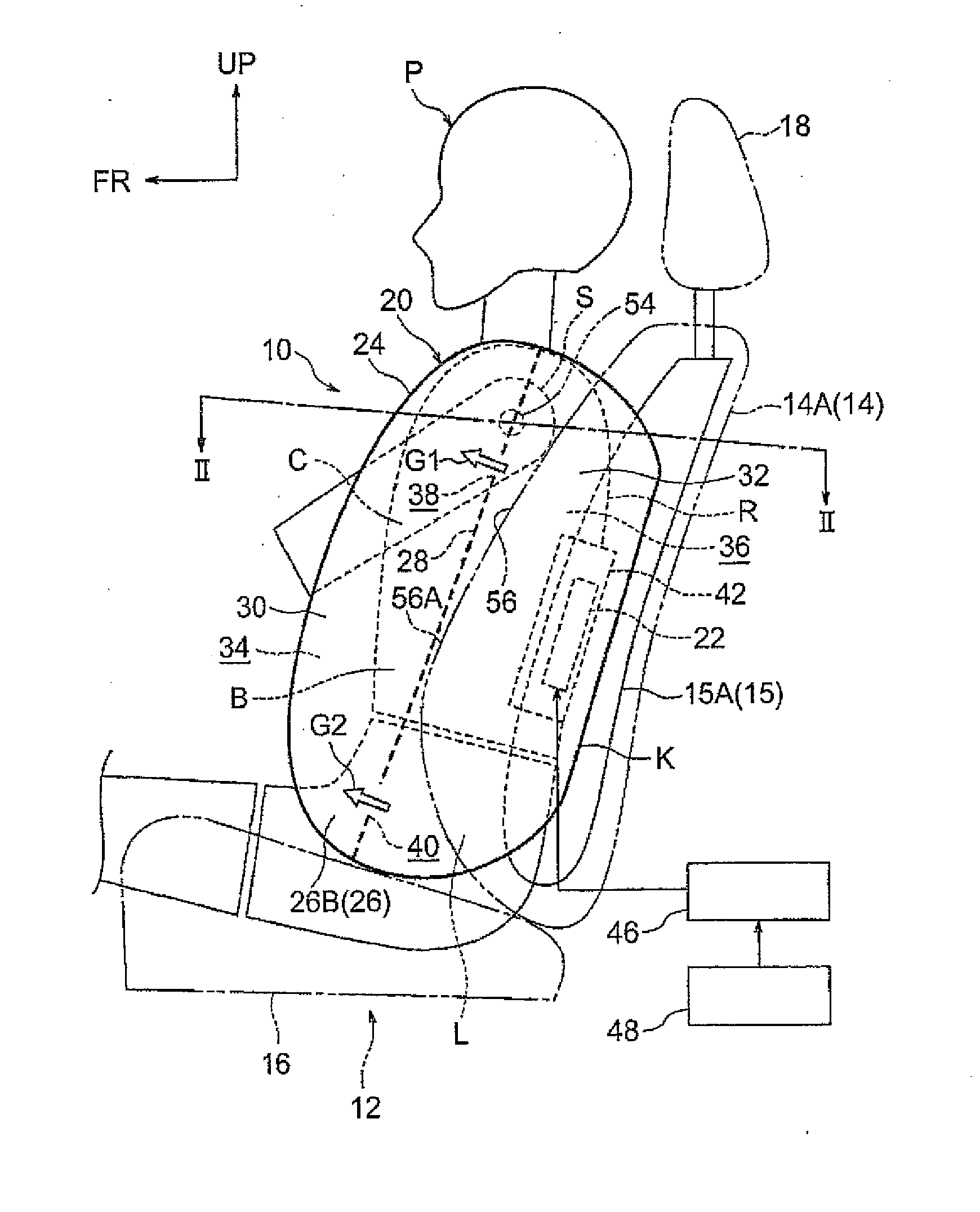
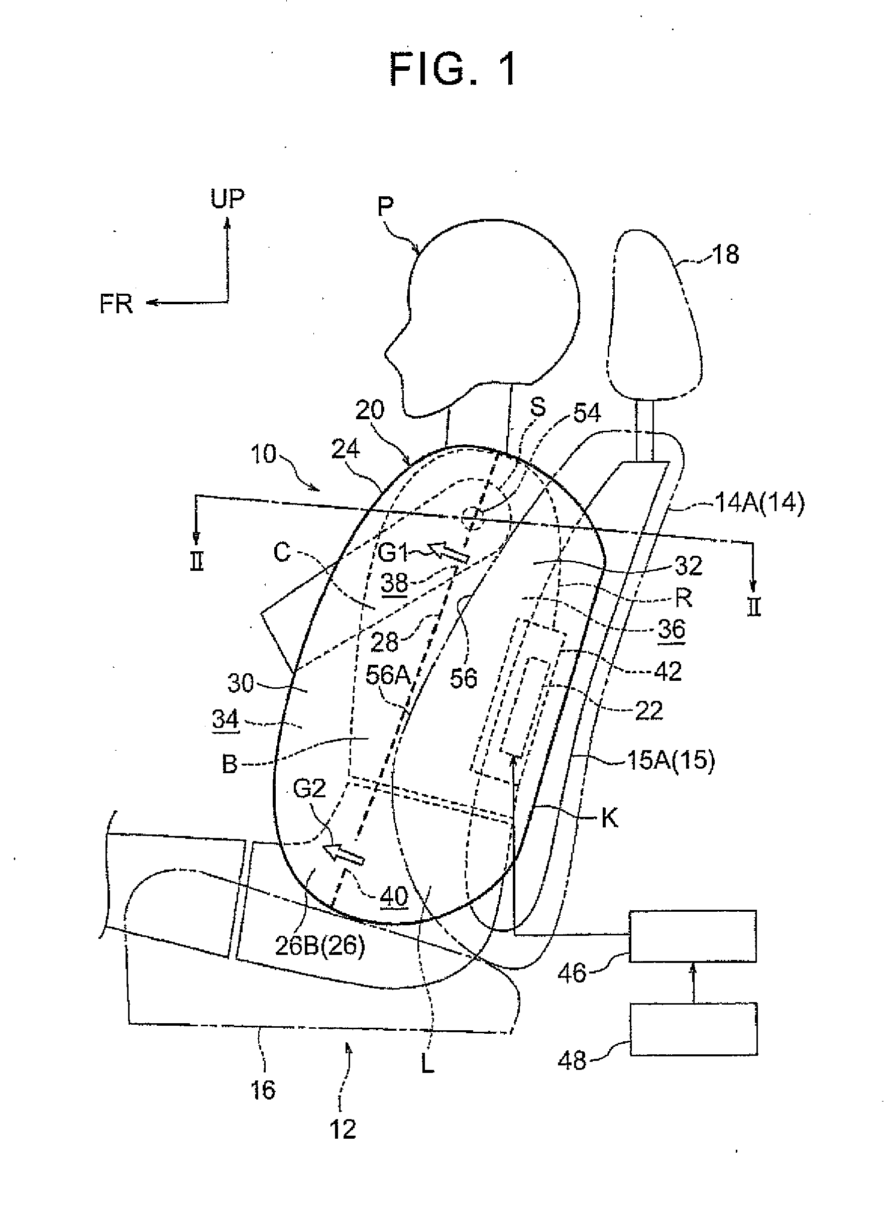
[0020]The following describes a vehicle side airbag device 10 according to a first embodiment of the present invention with reference to FIGS. 1 to 3. Note that an arrow FR, an arrow UP, and an arrow OUT, which are shown appropriately in each figure, indicate a vehicle front direction (a traveling direction), a vehicle upper direction, and an outer side in a vehicle width direction, respectively. Hereinafter, in a case where a description is made by use of merely front and rear directions, right and left directions, and upper and lower directions, they indicate front and rear sides in a vehicle longitudinal direction, right and left sides in a vehicle right-left direction (a vehicle width direction), and upper and lower sides in a vehicle up-down direction, respectively, unless otherwise specified.
Configuration
[0021]As illustrated in FIG. 1, the vehicle side airbag device 10 according to the present embodiment is provided in a door side portion 14A (an outer side portion in the vehi...
second embodiment
[0046]FIG. 4 is a side view illustrating an expanded unfolded state of a side airbag 62 in a vehicle side airbag device 60 according to a second embodiment of the present invention. In the side airbag 62, an inclined portion 28A extending diagonally downward toward a vehicle front side is provided in a lower part of a tether 28.
[0047]This embodiment basically has a configuration similar to the first embodiment except for the above configuration. Accordingly, even in the present embodiment, it is possible to obtain basically the same effect as the first embodiment. Besides, in the present embodiment, since the inclined portion 28A is provided in the lower part of the tether 28, a lower part of a rear bag portion 32 is enlarged toward the vehicle front side. Hereby, it is possible to improve restraining performance of the high-pressure rear bag portion 32 with respect to the lumbar L.
PUM
 Abstract
Description
Claims
Application Information