
Thermally activated adhesive and fixture for improving registration accuracy between assembled parts

Inactive Publication Date: 2011-04-21
APPLE INC
View PDF10 Cites 3 Cited by
  • Summary
  • Abstract
  • Description
  • Claims
  • Application Information

AI Technical Summary

Benefits of technology

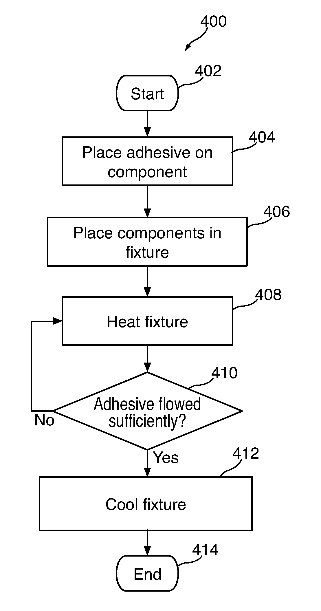
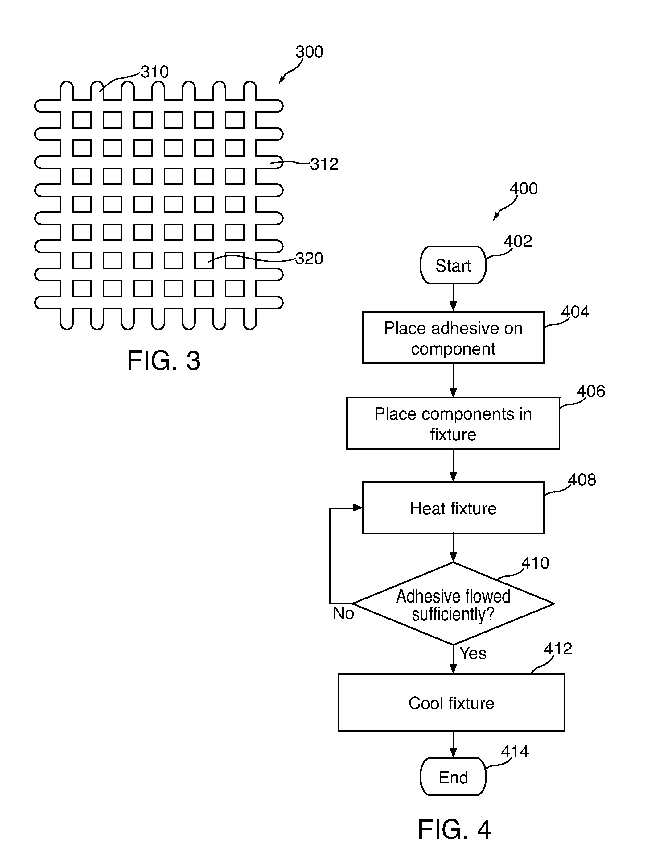
[0005]Some device housing components can be coupled to each other using an adhesive. To more particularly control the height between the housing components upon assembly, the components can be coupled using a thermally activated adhesive. In one implementation, a thermally activated adhesive can be applied to a thermally or a non-thermally conductive material such as a die cut sheet of material, or as a silk screen. The applied adhesive can be substantially solid, but have limited adhesive strength prior to being heated. When the adhesive is heated, the adhesive can flow and adhere to the housing components. Upon subsequent cooling, the adhesive can remain adhered to both components over a large surface area (e.g., due to the flowing of the adhesive).
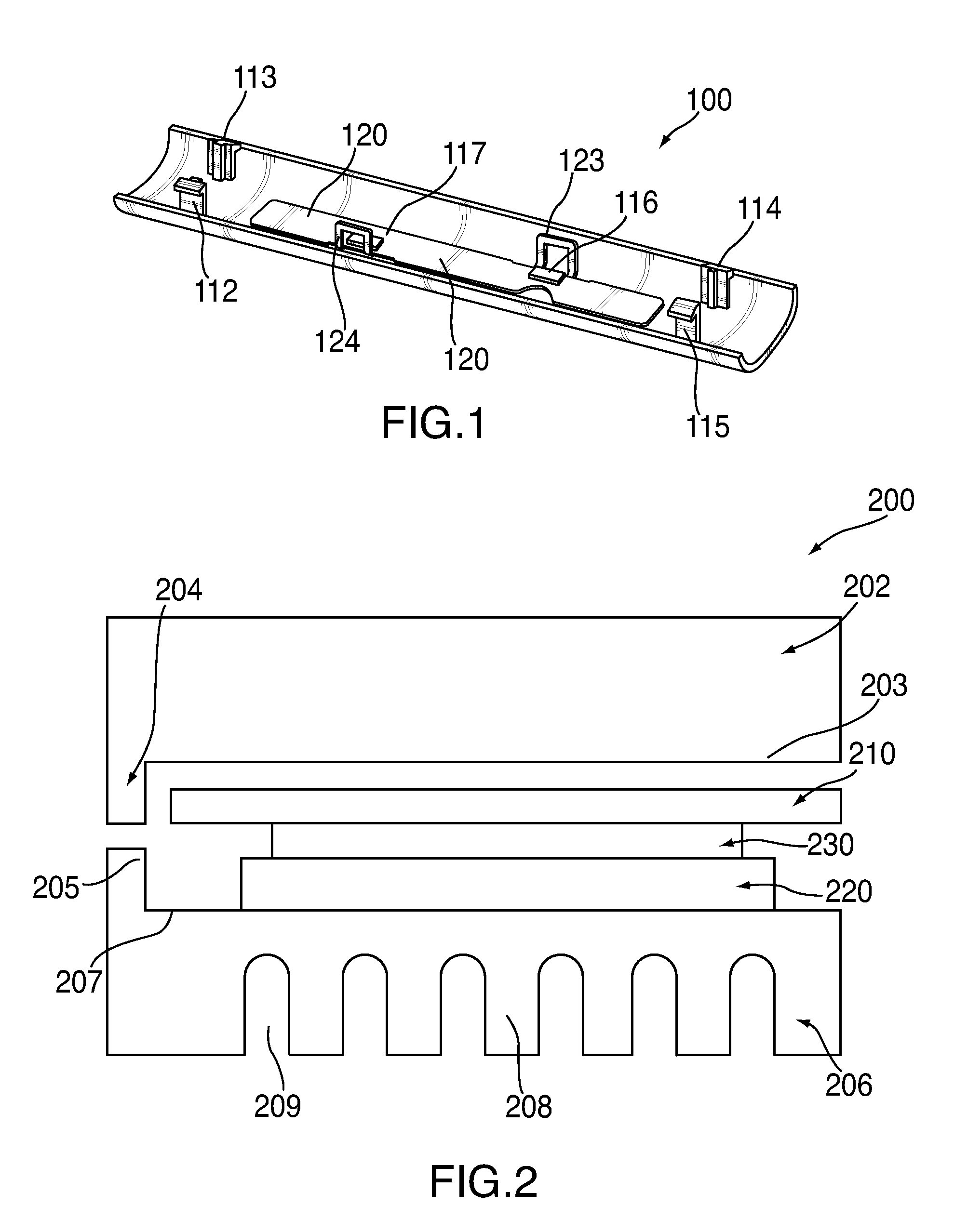
[0008]The adhesive can have any suitable thickness. In some embodiments, the thickness of the adhesive layer, and as a result the height of the stack that includes the two components being coupled and the adhesive, can be accurately defined using the fixture. In particular, the fixture can bring the components together to a desired height (e.g., as defined by a hard stop of the fixture). By heating and quickly cooling the adhesive when the desired stack height has been reached, the fixture can define a repeatable stack height with high tolerances. The solid state of the adhesive prior to heating, combined with the internal pockets for assisting adhesive flow can ensure that the interface between the components remains smooth.

Problems solved by technology

The applied adhesive can be substantially solid, but have limited adhesive strength prior to being heated.

Method used


Image

  • Thermally activated adhesive and fixture for improving registration accuracy between assembled parts
  • Thermally activated adhesive and fixture for improving registration accuracy between assembled parts
  • Thermally activated adhesive and fixture for improving registration accuracy between assembled parts

Examples


Embodiment Construction

[0014]An electronic device can be assembled by coupling different types of components. For example, a housing component can be coupled to circuitry or electronics providing features of the device. As another example, an assembly component can be coupled to a housing element (e.g., couple a hook to a housing component). The different components can be coupled in many different manners. If at least one of the components is thermally conductive, however, a thermally activated adhesive can be used. The thermally activated adhesive is substantially solid when cool, but flows and adheres when heated.

[0015]By placing the components with the thermally activated adhesive in a fixture, the adhesive can be heated and directed to flow between the components to ensure an adequate bond. In particular, heat can be applied or removed through one of the fixtures and through the thermally conductive component to activate or deactivate the adhesive. The fixture can include stops or other elements to e...


PUM

PropertyMeasurementUnit
Flow rateaaaaaaaaaa
Electrical conductoraaaaaaaaaa
Distanceaaaaaaaaaa

Abstract

This is directed to a method for assembling components using a thermally activated adhesive. Two components of an electronic device housing can be coupled as part of the electronic device assembly. At least one of the two components can be thermally conductive. To use a thermally conductive adhesive to couple the components, the components can be placed in a fixture, and the adhesive between the components. The fixture can then be heated such that heat from the fixture is conducted through the thermally conductive component and into the adhesive. The adhesive can flow and propagate between the components. When the adhesive layer has flowed into an adequate layer, the fixture can be cooled such that heat can be removed from the adhesive through the thermally conductive component. The adhesive can harden and secure the components to each other.

Description

BACKGROUND OF THE INVENTION[0001]This is directed to a method and fixture for assembling at least one thermally conductive component to another component using a thermally activated adhesive. In particular, this is directed to a thermally activated adhesive having integrated pockets into which the adhesive can flow.[0002]An electronic device enclosure can include several components that are assembled to each other. In some embodiments, a thermally conductive material (e.g., a metal) can be coupled to a thermally isolating material (e.g., a plastic). For example, an electronic device housing can include a housing constructed from plastic. The housing can be coupled to a frame via a series of metal hooks coupled to the housing. The metal hooks can be coupled to the housing any suitable approach. In some embodiments, a heat staking process can be used. Alternatively, a liquid adhesive can be used. As still another example, a mechanical fastener (e.g., screws) can be used.[0003]These ap...

Claims


Application Information

Patent Timeline
IPC IPC(8): B29C65/52B29C65/02
CPCB29C65/44B29C65/5007B29C65/5057B29C65/526B29C66/0342B29C66/234B29C66/92655B29C66/7422B29C66/74283B29C66/8322B29C66/92653C09J5/06B29C65/4815B29C66/742
Inventor FRAZIER, CAMERON
Owner APPLE INC
Learn More