Method and apparatus for a surround view camera system photometric alignment

a camera system and photometric alignment technology, applied in the field of methods and apparatus for surround view camera system photometric alignment, can solve the problems of inconsistent brightness and unnatural color transition of composite images, and achieve the effect of optimal color gain

Active Publication Date: 2015-05-21
TEXAS INSTR INC
View PDF2 Cites 42 Cited by
  • Summary
  • Abstract
  • Description
  • Claims
  • Application Information

AI Technical Summary

Benefits of technology

This patent describes a way to create an improved surrounding visual representation by combining multiple images taken through different cameras into a single video that gives a wider perspective than any individual camera can provide alone. The process involves analyzing each image and finding common elements among them, which are then used to estimate how much color should be added or changed to make everything look better when combined. Once all these changes have been made, the resulting video looks like it was captured with just one camera but has more detail and greater depth of field.

Problems solved by technology

Surround view camera systems are used to improve safety when driving by providing a wide angle view based on multiple cameras placed around the vehicle. However, these images often have uneven lighting and colors because each camera faces a different direction. Therefore, there is a technical problem with how to fix this issue and make the surrounding environment appear consistent and accurate.

Method used


Image

  • Method and apparatus for a surround view camera system photometric alignment
  • Method and apparatus for a surround view camera system photometric alignment
  • Method and apparatus for a surround view camera system photometric alignment

Examples


Embodiment Construction

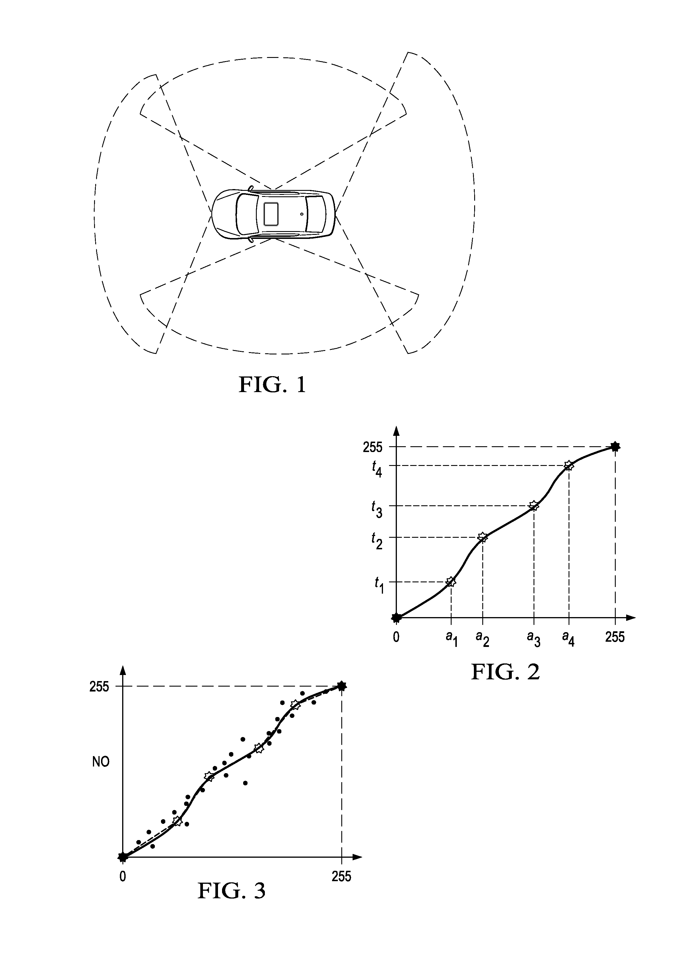
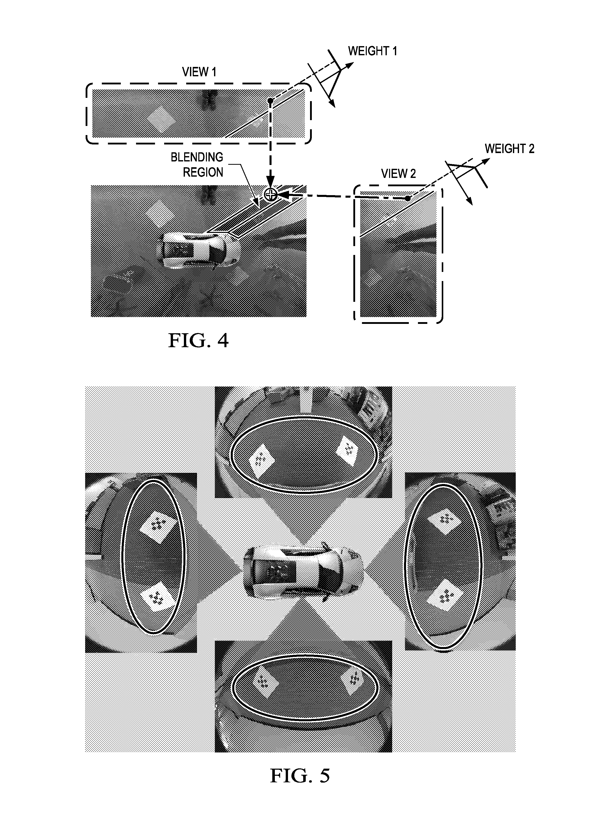
[0027]To correct a photometric misalignment across the views globally and locally, the method and apparatus described herein apply a color adjustment and gain correction. In one embodiment, the method and apparatus also apply tone curve refinement. The color adjustment algorithm globally aligns the brightness and color of each individual view to reduce the visibility of seam in the composite view. To eliminate the visibility of seams, local blending is applied where adjacent views are stitched.

[0028]For blending, there are three options: (1) one is a basic linear blending scheme, (2) selective blending, and (3) multi-band blending. The suitable option is used based on the computation complexity requirement and quality requirement.

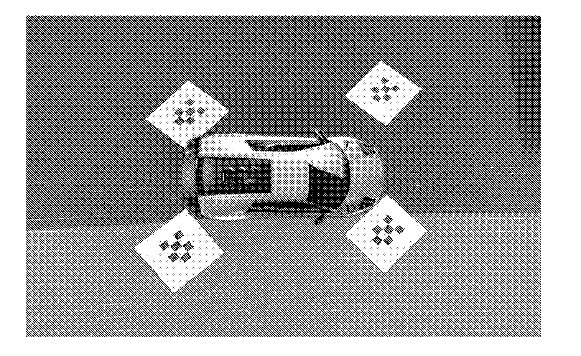
[0029]Usually, the input to our photometric alignment algorithm are: the fish-eye images directly from the cameras, the geometric look-up table (LUT) generated from the calibration module of the surround view camera system, and the coordinate information sp...


PUM


Abstract

A method, apparatus and a surround view camera system. The method includes extracting block samples from at least one of a composite view geometric LUT, input fish-eye image and view overlapping region, selecting sample inliers from the extracted block samples, estimating optimal color gain for the selected block samples, performing refined adjustment based on the estimated color gain and applying color transform, and producing a composite surround view image.

Description


Claims


Application Information

Patent Timeline
Owner TEXAS INSTR INC
Why Eureka
Try Eureka