Ureteral stent for placement in a kidney and bladder

Active Publication Date: 2015-05-21
UNIV HOSPITALS HEALTH SYST
View PDF39 Cites 18 Cited by
  • Summary
  • Abstract
  • Description
  • Claims
  • Application Information

AI Technical Summary

Benefits of technology

[0005]The present invention provides a ureteral stent including a bladder portion positioned in a bladder of a patient, a kidney portion positioned in a kidney and ureteral passageway of the patient, and one or more tethers coupling the bladder portion to the kidney portion. The ureteral stent allows urine to pass around a blockage, and al

Problems solved by technology

These passageways can become blocked by tumors or kidney stones thereby preventing normal u

Method used


Image

  • Ureteral stent for placement in a kidney and bladder
  • Ureteral stent for placement in a kidney and bladder
  • Ureteral stent for placement in a kidney and bladder

Examples


Embodiment Construction

[0043]The principles of the present application have particular application to ureteral stents for unblocking a ureteral passageway and thus will be described below chiefly in this context. It will, of course, be appreciated and also understood that the principles of the application may be useful in other medical applications, such as other stent applications, for example biliary stents.

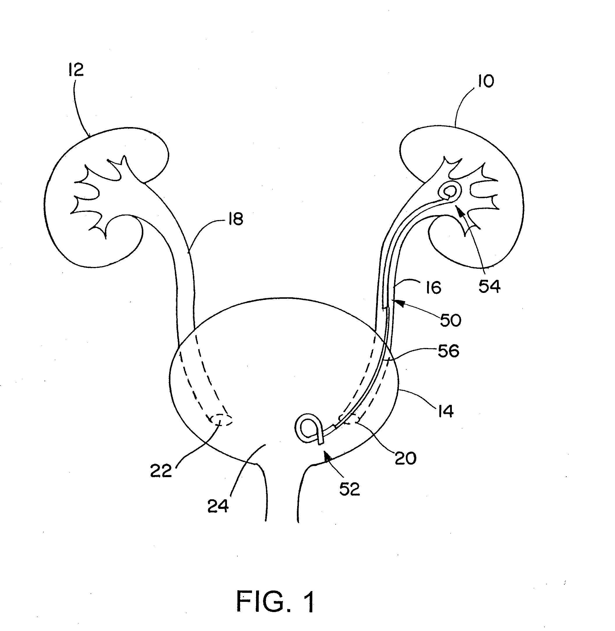
[0044]Referring now in detail to the drawings and initially to FIG. 1, a pair of kidneys 10 and 12 and a bladder 14 of a patient are shown. The kidneys 10 and 12 are connected to the bladder 14 by respective ureteral passageways 16 and 18. The ureteral passageways 16 and 18 each include a portion extending into the bladder 14 that moves from an uncompressed state to compressed state and in a normal state only allows urine to pass from the kidneys 10 and 12 to the bladder 14 with the help of peristalsis of the ureter. When one of the passageways 16 and 18 becomes blocked, for example by swelling near ...


PUM


Abstract

Provided is a ureteral stent (=50) including a bladder portion (=52) positioned in a bladder of a patient, a kidney portion (=54) positioned in a kidney and ureteral passageway of the patient, and one or more tethers (=56) coupling the bladder portion to the kidney portion. The ureteral stent allows urine to pass around a blockage, and allows a ureter orifice connecting the ureteral passageway to the bladder to move between a compressed state and an uncompressed state to prevent or minimize urinary reflux, flank pain, blood in the urine, etc., while allowing the bladder portion to move freely in the bladder to prevent the bladder portion from irritating the trigone muscle.

Description

RELATED APPLICATIONS[0001]This application claims the benefit of U.S. Provisional Application No. 61 / 657,228 filed Jun. 8, 2012, which is hereby incorporated herein by reference.FIELD OF INVENTION[0002]The present invention relates generally to implantable medical devices, and more particularly to stents, such as ureteral stents.BACKGROUND[0003]The urinary tract has a pair of kidneys that connect to a bladder by ureteral passageways, and a urethra that extends from the bladder to the exterior of a patient. Urine is made by the kidneys, passed through the ureteral passageway, stored in the bladder and ultimately voided from the urethra. A urinary sphincter is positioned around the urethra near the base of the bladder to control the flow of urine from the bladder.[0004]The ureteral passageways normally allow urine to pass from the kidney to the bladder by peristalsis. When the bladder fills with urine, the bladder compresses a segment of the ureteral passageway that passes through a w...

Claims


Application Information

Patent Timeline
IPC IPC(8): A61F2/82
CPCA61F2/82A61F2220/0008A61F2250/0018A61F2250/0098A61F2220/0075A61M27/008A61F2230/0041A61F2230/0069A61F2250/0039A61F2230/0006A61F2250/0029A61F2250/0014A61F2250/0006A61F2250/0036A61F2220/005A61F2250/006A61F2230/0013A61F2250/0019A61F2002/048A61F2002/047
Inventor PONSKY, LEE E.SECREST, DEAN
Owner UNIV HOSPITALS HEALTH SYST
Why Eureka
Try Eureka