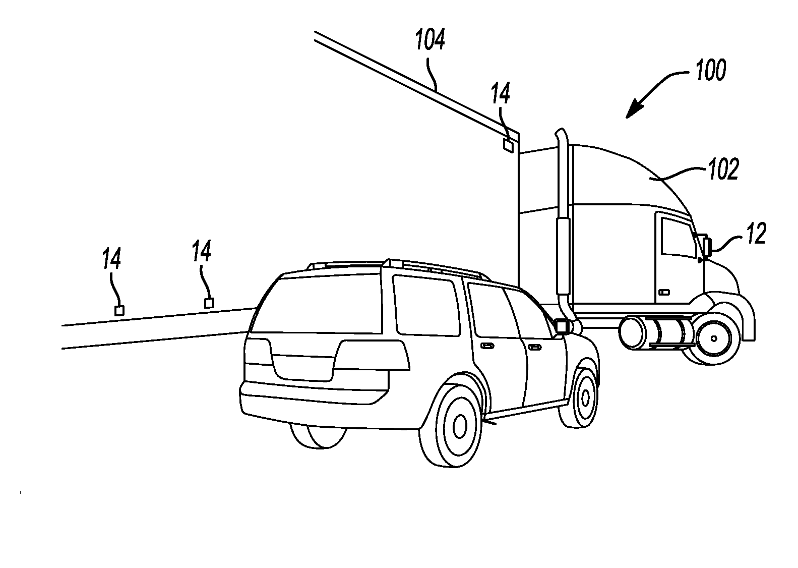
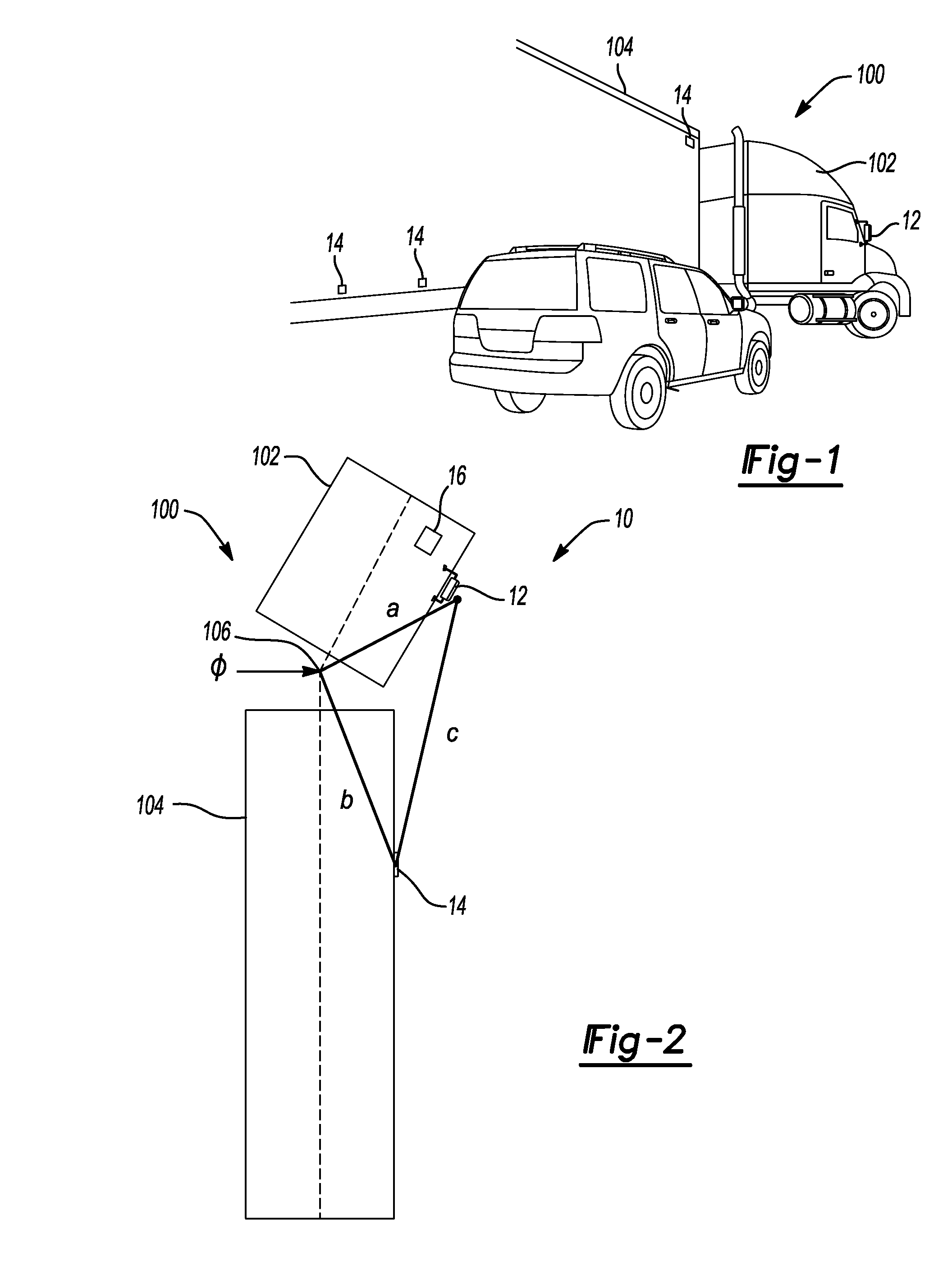
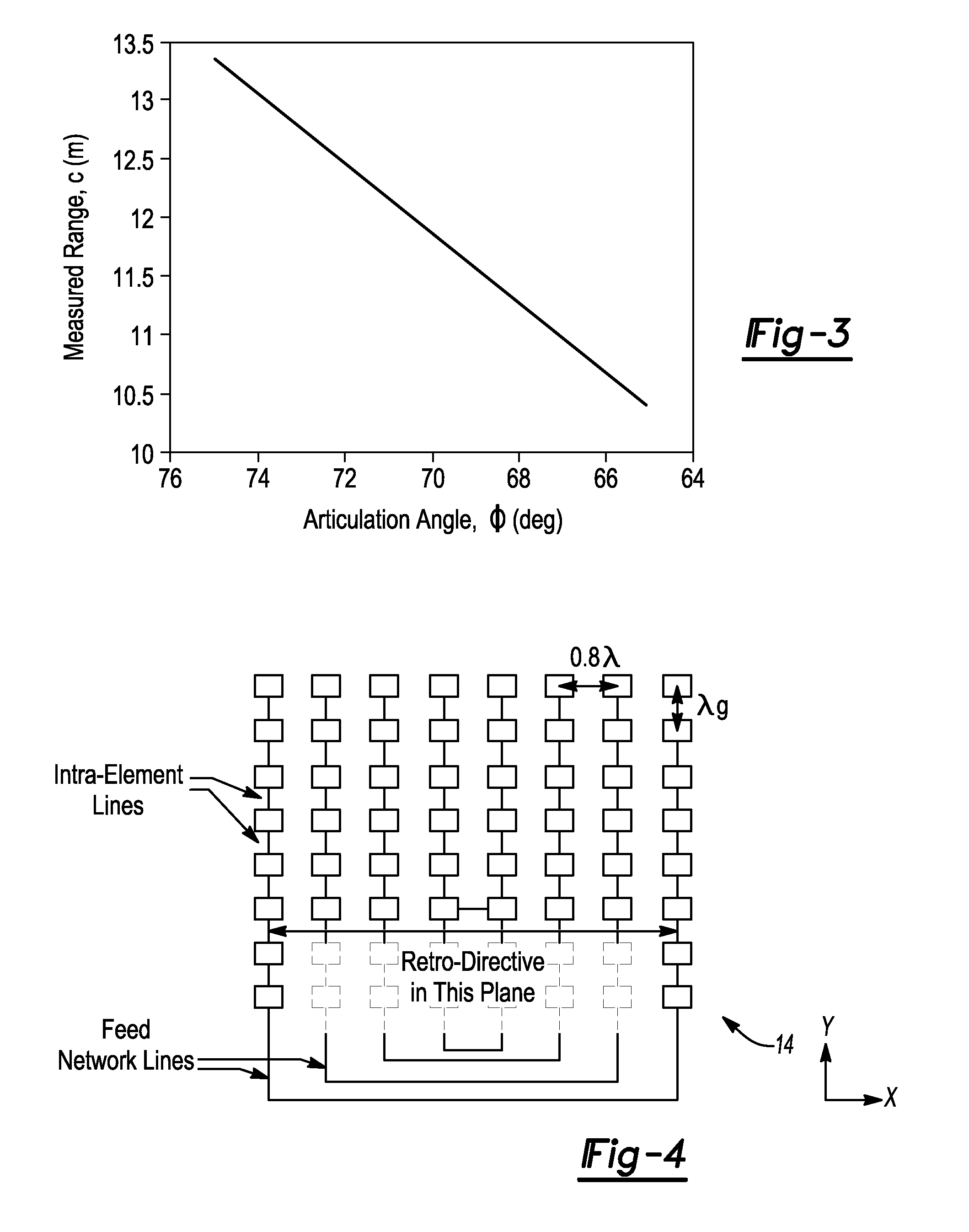
Retro-reflective radar patch antenna target for articulated vehicle trailer sensing

a technology of retroreflective radar and target system, which is applied in the field of vehicle sensing, can solve the problems of difficult to determine the precise location of all parts of the articulated vehicle, and difficulty in determining position data during operation

Inactive Publication Date: 2015-05-28
MICHIGAN TECHNOLOGICAL UNIVERSITY +1
View PDF10 Cites 9 Cited by
  • Summary
  • Abstract
  • Description
  • Claims
  • Application Information

AI Technical Summary

Benefits of technology

[0037]In automotive applications, the vehicles, roadways and roadside signs, reflect RF waves with the same polarization as transmitted (co-polarization). Th...

Problems solved by technology

However, in the case of oversized vehicles and/or articulating vehicles, such as tractor-trailer configurations (e.g. semi-trucks and oversized carriers), determining position data during operation can be difficult.
As an articulated vehicle ...

Method used


Image

  • Retro-reflective radar patch antenna target for articulated vehicle trailer sensing
  • Retro-reflective radar patch antenna target for articulated vehicle trailer sensing
  • Retro-reflective radar patch antenna target for articulated vehicle trailer sensing

Examples


Embodiment Construction

[0016]Example embodiments will now be described more fully with reference to the accompanying drawings.

[0017]Example embodiments are provided so that this disclosure will be thorough, and will fully convey the scope to those who are skilled in the art. Numerous specific details are set forth such as examples of specific components, devices, and methods, to provide a thorough understanding of embodiments of the present disclosure. It will be apparent to those skilled in the art that specific details need not be employed, that example embodiments may be embodied in many different forms and that neither should be construed to limit the scope of the disclosure. In some example embodiments, well-known processes, well-known device structures, and well-known technologies are not described in detail.

[0018]The terminology used herein is for the purpose of describing particular example embodiments only and is not intended to be limiting. As used herein, the singular forms “a,”“an,” and “the” ...


PUM


Abstract

A vehicle detection system for determining the position of a trailing section relative to a forward section of a vehicle, such as a tractor-trailer combination. The trailing section is pivotally coupled to the forward section for driving movement therewith. The vehicle detection system includes a central controller and a detection system connectable to the forward section of the vehicle and operably coupled to the central controller. The detection system outputs a detection signal. A target device is connectable to the trailing section and configured to receive the detection signal from the detection system and output a unique return signal to the detection system. The detection system receives the return signal and transfers the return signal or other indicative signal for processing by the central controller, whereby the central controller determines position information of the trailing section, for potential use by a DSRC.

Description

CROSS-REFERENCE TO RELATED APPLICATIONS[0001]This application claims the benefit of U.S. Provisional Application No. 61 / 908,845, filed on Nov. 26, 2013. The entire disclosure of the above application is incorporated herein by reference.FIELD[0002]The present disclosure relates to vehicle sensing and, more particularly, relates to vehicle position sensing of articulated vehicles using a retro-reflective radar patch antenna target system.BACKGROUND AND SUMMARY[0003]This section provides background information related to the present disclosure which is not necessarily prior art. This section provides a general summary of the disclosure, and is not a comprehensive disclosure of its full scope or all of its features.[0004]Dedicated short-range communication (DSRC) is a one-way or two-way short- to medium-range wireless communication standard specifically designed for automotive use and includes a corresponding set of protocols and standards. DSRC is particularly useful as a means to enab...

Claims


Application Information

Patent Timeline
IPC IPC(8): G01S13/93G01S13/75G01S13/931
CPCG01S13/931G01S2013/9332G01S13/751G01S7/024G01S13/88G01S2013/93274G01S2013/9315G01S7/4095G01S7/4091
Inventor MADDOX, JOHN M.BULLER, WILLIAM
Owner MICHIGAN TECHNOLOGICAL UNIVERSITY
Why Eureka
Try Eureka