Stud

a technology of studs and screws, applied in the direction of fastening means, screws, electrical equipment, etc., can solve the problems of easy finger injury, difficult fixation or detachment of studs, and inability to rotate the stud smoothly by fingers, so as to improve production efficiency, facilitate operation, and facilitate the effect of us

Inactive Publication Date: 2015-06-04
GIGA BYTE TECH CO LTD
View PDF19 Cites 10 Cited by
  • Summary
  • Abstract
  • Description
  • Claims
  • Application Information

AI Technical Summary

Benefits of technology

[0012]Through the present invention, the stud with the tooling groove can be selectively by using fingers or the hand tool according to the user requirement, such that the stud can be fixed to the case or detached from the case in two ways, and that is more utilization and convenience. Furthermore, each stud is able to be directly fixed to the case or detached from the case by the screwdriver, so that the operation procedure is simple and convenient, thus the user can be operating intuitively and quickly, such that the production efficiency is improved.

Problems solved by technology

However, if the studs need to be disposed in a narrow place or the both sides of the studs have the high components, it causes the stud can not be rotated smoothly by fingers, and more difficult to fix or detach the studs, also may be hurting the fingers easily.
However, due to the above studs which must be combined with the tool head to fix or detach the stud by the hand tool, such that the operation procedure is troublesome and time-consuming, and must be making the tool heads for various sizes, Therefore, the user can not be operating intuitively, which can not be fixed or detached easily and quickly, also increased the production costs.
Besides, some inconvenience may be generated if the tool heads are lost.
Therefore, how to make the stud fixed or detached, that can be selectively by using fingers or hand tool according to the user requirement and simple operation procedures is an important issue for the manufactures of studs.

Method used


Image

  • Stud
  • Stud
  • Stud

Examples


Embodiment Construction

[0023]This disclosure includes three embodiments. In these three embodiments, a stud 100 will be combined with different appearance of the structure for illustration. People having ordinary skill in the art can make proper modification to the appearance of the stud 100 according to the actual needs or design requirements, not limited as described herein.

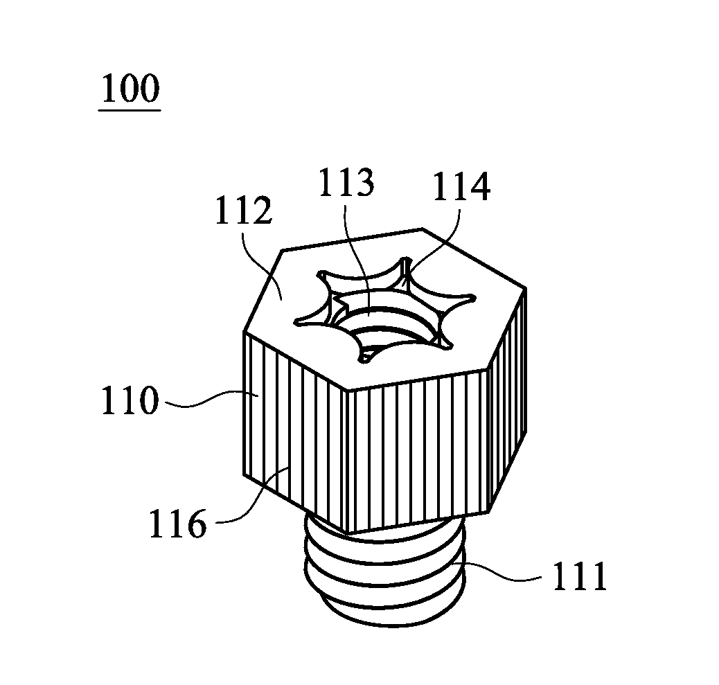
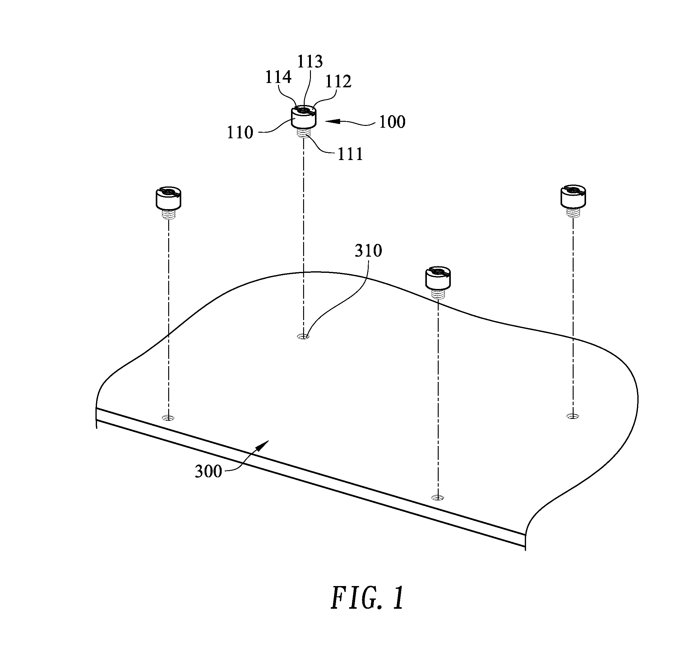
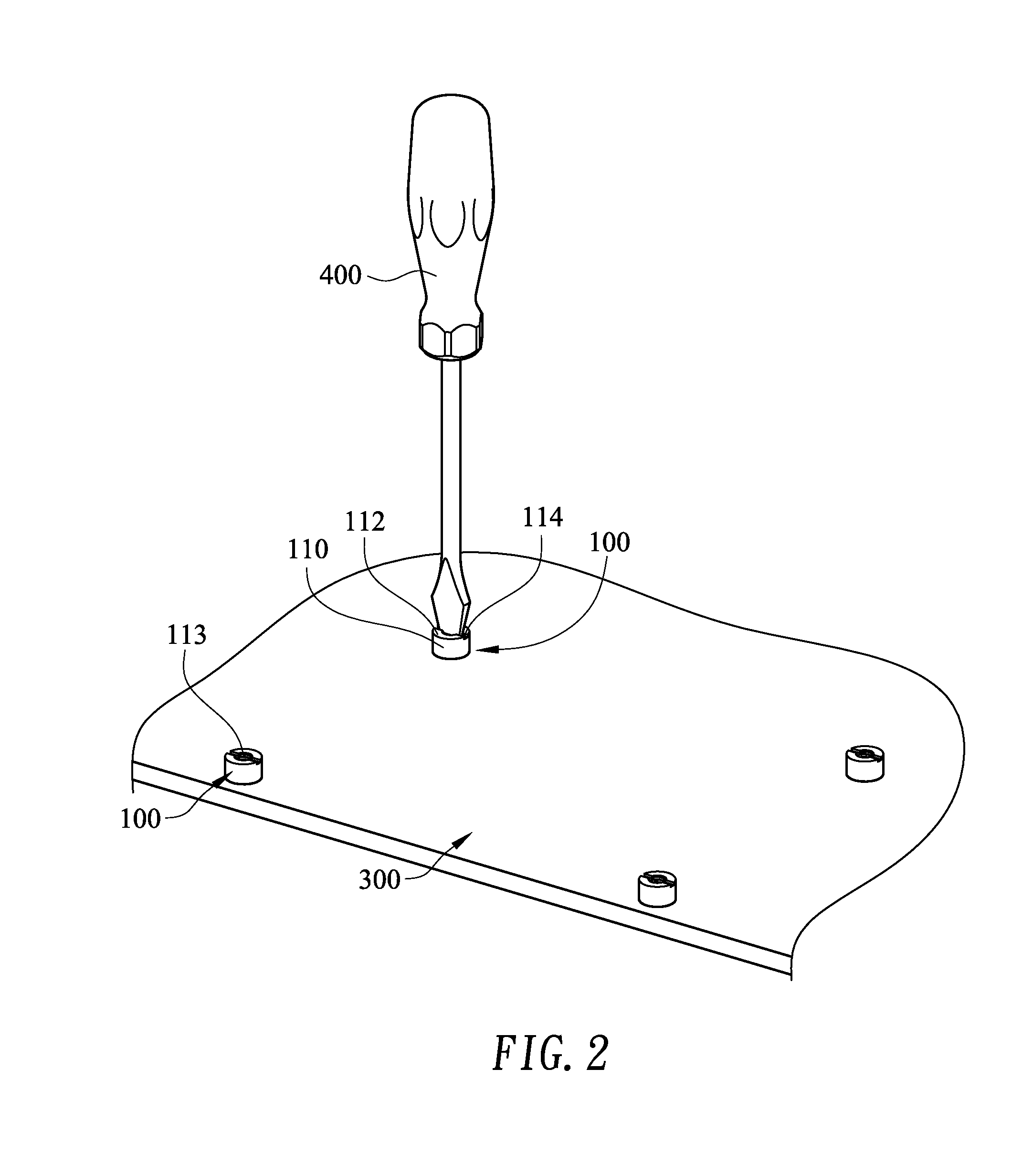
[0024]FIGS. 1 to 4 are exploded view and perspective view of the studs 100 of the first embodiment. The stud 100 is used to support a circuit board 200 on the case 300 of an electronic device. The circuit board 200 has a locating hole 210. It is noted that in the following embodiments the circuit board 200 is but not limited to a motherboard. The case 300 of the electronic device is provided with a tapped hole 310, and the motherboard is used as an exemplary interpretation of the studs 100 without any intention to limit the scope of the present invention. The electronic device described in the embodiments, such as a computer host, an...


PUM


Abstract

A stud used to support a circuit board on a case, the case has a tapped hole, and the circuit board has a locating hole. The stud includes a main body. The main body includes a screw thread portion and a carrying surface, wherein the main body is fixed to the tapped hole of the case by the screw thread portion, and the carrying surface withstands the circuit board, the carrying surface has an opening and a tooling groove, the opening is corresponding to the locating hole of the circuit board. A hand tool is inserting into the tooling groove of main body, and the shape of the hand tool corresponds to the shape of the tooling groove, so that the main body is able to be fixed to the case or detached from the case by the hand tool.

Description

CROSS-REFERENCES TO RELATED APPLICATIONS[0001]This non-provisional application claims priority under 35 U.S.C. §119(a) on Patent Application No. 102222612 filed in Taiwan, R.O.C. on Dec. 02, 2013, the entire contents of which are hereby incorporated by reference.BACKGROUND OF THE DISCLOSURE[0002]1. Field of the Invention[0003]The disclosure relates to a stud, and more particularly to a stud with a tooling groove for fixing a circuit board.[0004]2. Description of Related Art[0005]The electronic devices set different sizes of studs on the cases, and these studs are used to support the circuit boards or the interface cards, so that the circuit board and the interface card can keep at a position, and the elements of the bottom of the circuit board / interface card will not be pressed to the case, also the circuit board / interface card can be located and fixed on the case of electronic device that to ensure each circuit board or interface card can operate normally.[0006]Most of the studs ca...

Claims


Application Information

Patent Timeline
Patent Type & Authority Applications(United States)
IPC IPC(8): F16B23/00
CPCF16B23/0007F16B5/065H05K7/142F16B5/0233F16B23/0015F16B23/003F16B23/0038F16B37/125
Inventor LAI, CHIH-MINGCHIANG, CHUNG WEI
Owner GIGA BYTE TECH CO LTD
Why Eureka
Try Eureka