Control device for gas taps

Active Publication Date: 2015-06-04
ELTEK
View PDF17 Cites 81 Cited by
  • Summary
  • Abstract
  • Description
  • Claims
  • Application Information

AI Technical Summary

Benefits of technology

[0012]The object of the present invention is to overcome one or more of the drawbacks referred to above and to provide a control device for gas taps, of the type referred to above,

Problems solved by technology

This solution is relatively inconvenient, for example when the timing function is active for a plurality of the devices associated to the taps.
Display of information for a number of devices on a single display complicates the control and data-communication logic.
The possible simultaneous display of information on a number

Method used


Image

  • Control device for gas taps
  • Control device for gas taps
  • Control device for gas taps

Examples


Example

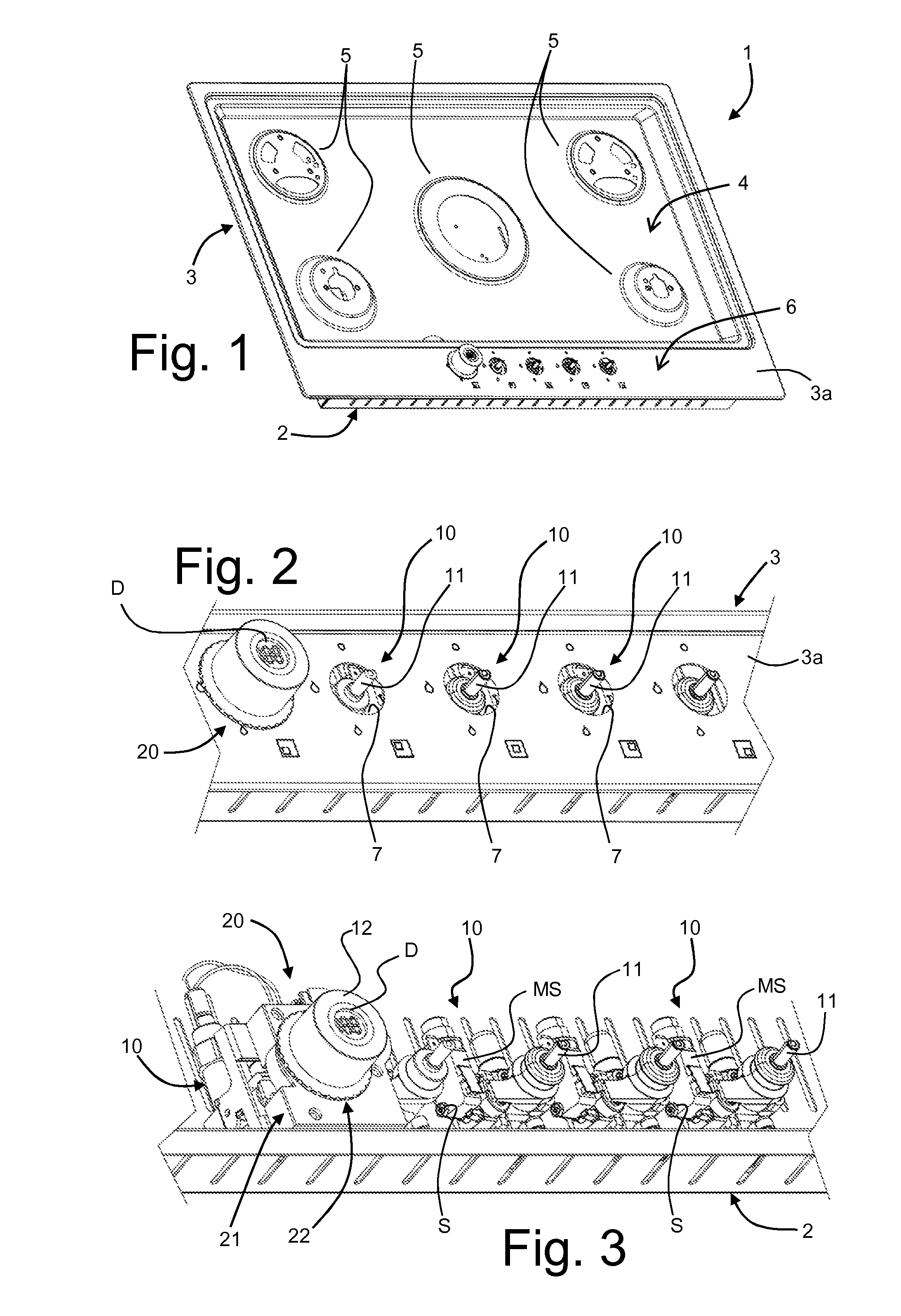
[0044]FIG. 1 is a schematic representation of a gas-supplied appliance 1, equipped with a control device according to the present invention, hereinafter also defined for ready reference as “timer device”.

[0045]In the example illustrated, the appliance 1 is a cooking appliance, and more in particular a cooking hob, of a general conception in itself known, of which just the elements useful for an understanding of the invention are represented. The timer device according to the invention may in any case also be used in other types of appliances provided with at least one gas burner, or similar flame generator, controlled via a respective tap, such as for example boilers, in particular for domestic heating.

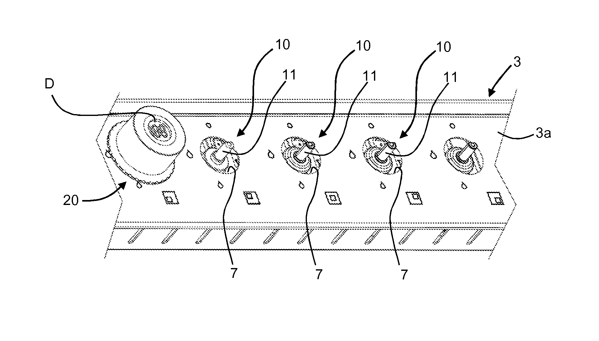
[0046]The structure or body of the appliance 1 includes a lower box 2, which is fixed to an upper lid 3, defining a working area 4 identified in which are various cooking locations 5, as well as a command area 6. As per the known art, mounted within the structure of the appliance 1 ar...


PUM


Abstract

A control device for gas appliances comprises:
    • a manual-control element (12, 22);
    • a circuit arrangement that includes control elements, electrical-interconnection elements, detection elements configured for detecting actuation of the manual-control element (12, 22) and supplying corresponding signals to the control elements; and
    • a supporting structure that can be associated in a stationary way with respect to a gas tap (10), wherein the supporting structure includes a first part of stationary structure (21) that defines a housing for at least part of the circuit arrangement, the first part of structure being in particular designed for being housed within a body (3) of the gas appliance.
The control elements are designed for counting the time, the circuit arrangement includes display elements (D′), and the supporting structure includes a second part of stationary structure (43, 44) associated to or projecting from the first part of structure (21) and configured for supporting the display elements (D) in a fixed or not angularly rotatable position, where in particular, in an installed condition of the device (20), the second part of structure (43, 44) projects on the outside of the body (2, 3) of the gas appliance (1).

Description

FIELD OF THE INVENTION[0001]The present invention relates to devices for control and / or detection of the supply of gas for appliances having one or more gas burners or similar flame generators. More in particular, the invention regards a control and / or detection device having a timing function, for example for enabling setting and / or adjustment and / or detection of a desired time interval of supply of gas to a respective burner or the like and / or for controlling and / or detecting the time that the burner remains lit.PRIOR ART[0002]Gas taps commonly used in cooking appliances and the like have a body, generally made of metal, provided with an inlet for connection to a gas-supply line, and an outlet for connection to a duct for delivery of the gas to the burner controlled by the tap. Mounted within the tap body are means for adjusting the flow of gas, constituted, for example, by an open / close element or partializer that can be position-adjusted via a maneuvering rod and / or further leve...

Claims


Application Information

Patent Timeline
IPC IPC(8): F24C3/12
CPCF24C3/126F23N5/107F23N5/203H01H19/025
Inventor MORO, MARCOSAVINI, PAOLO
Owner ELTEK
Why Eureka
Try Eureka