Electronic mirror device

a technology of electronic mirror and mirror, which is applied in the field of electronic mirror devices, can solve the problems of user discomfort and inability to use the same way of electronic mirrors

Inactive Publication Date: 2015-06-04
PANASONIC INTELLECTUAL PROPERTY MANAGEMENT CO LTD
View PDF7 Cites 20 Cited by
  • Summary
  • Abstract
  • Description
  • Claims
  • Application Information

AI Technical Summary

Benefits of technology

[0012]An electronic mirror device according to an aspect of the present disclosure can shift an image display location to a location where the user can view the image easily, thus allowing the user to look at easily even a facial part (such as his or her profile or a part under his or her chin) which is usually hard to see in a normal mirror.

Problems solved by technology

However, the electronic mirror cannot be used in exactly the same way as a normal mirror, which makes the user feel somewhat uncomfortable especially when the camera is not level with his or her eyes (i.e., his or her line of sight is not aligned with the camera), which is one of problems with the electronic mirror.

Method used


Image

  • Electronic mirror device
  • Electronic mirror device
  • Electronic mirror device

Examples


embodiment 1

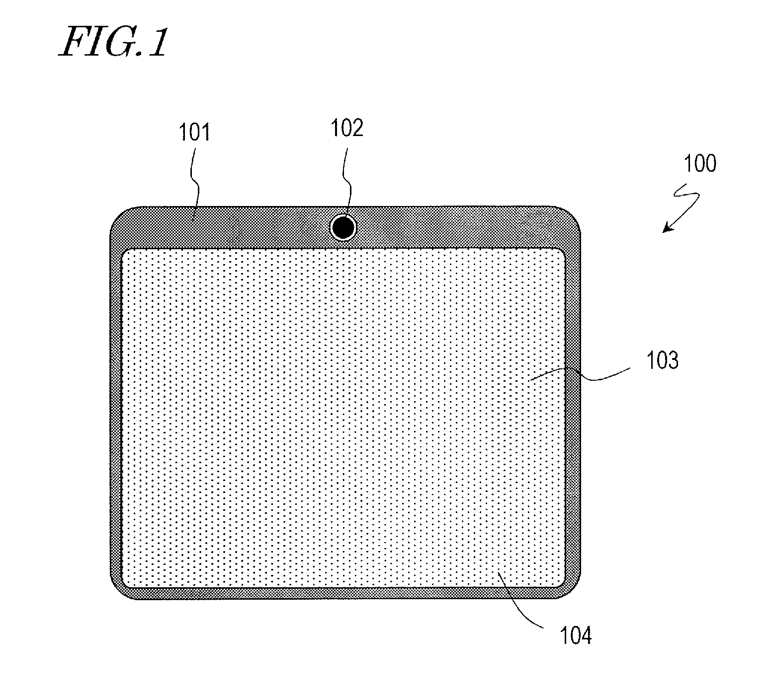
[0042]FIG. 1 illustrates an electronic mirror device 100 as a first embodiment. This electronic mirror device 100 displays a user's facial mirror image, and includes a housing 101, an image capturing section 102, a display section 103 which displays an image that has been captured by the image capturing section 102, and a touchscreen panel 104 which accepts the user's touch manipulation. The touchscreen panel 104 is a kind of user interface which accepts various instructions given by the user such as an instruction to shift the location where the image is displayed. In this example, the image capturing section 102, display section 103 and touchscreen panel 104 are housed in the same housing 101 and form integral parts of this electronic mirror device.

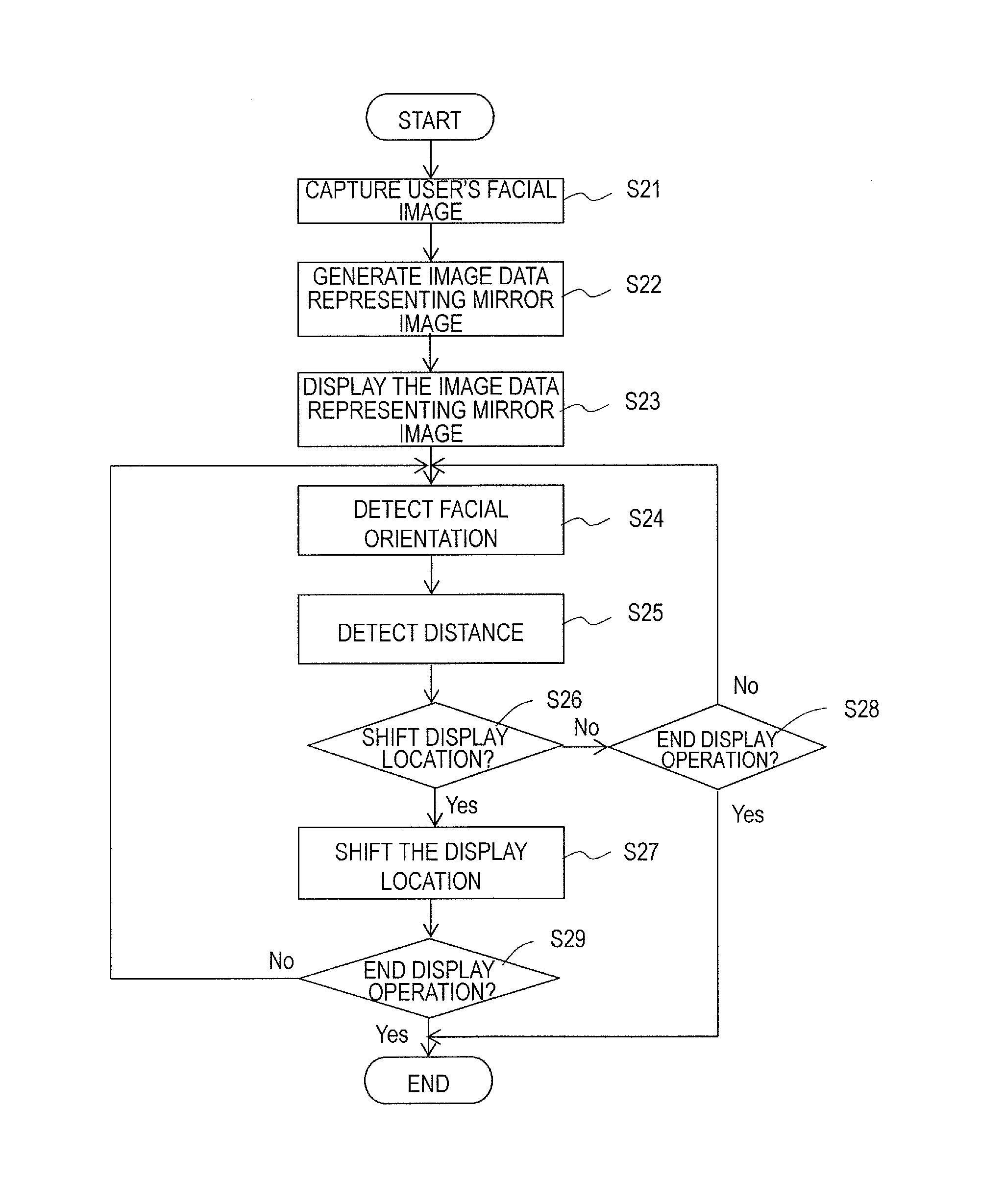
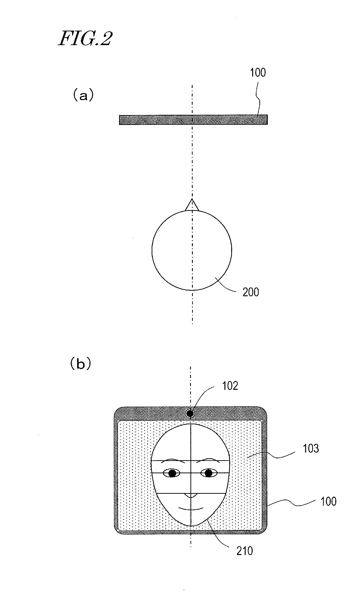
[0043]Next, it will be described with reference to FIGS. 2 and 3 how this electronic mirror device 100 works. FIGS. 2(a) and 3(a) show relative positions of the electronic mirror device 100 and a user 200 as viewed from over them. On th...

embodiment 2

[0066]FIG. 9 illustrates an electronic mirror device 100 as a second embodiment. The electronic mirror device 100 of this embodiment has so small a size as to be portable. The electronic mirror device 100 may be a smartphone or tablet terminal in which an application that makes the device 100 operate as an electronic mirror has been installed. In the electronic mirror device 100 of this second embodiment, the angle detecting section 105 senses how this electronic mirror device 100 is held by the user 200.

[0067]Now it will be described with reference to FIG. 9 how this electronic mirror device 100 works. Supposing a state where the electronic mirror device 100 is arranged so that its longitudinal direction is perpendicular to the horizontal direction and its image capturing section 102 is located at the top as shown in FIG. 9(a) is a reference state, the facial image 210 is displayed in the upper area of the display section 103 because the closer to the image capturing section 102 th...

embodiment 3

[0073]An electronic mirror device 100 as a third embodiment will be described with reference to FIGS. 12 through 15.

[0074]FIG. 12(a) is a top view of an electronic mirror device 100 according to this third embodiment, and FIG. 12(b) is a plan view illustrating the electronic mirror device 100 of the third embodiment as viewed in front of its display section 103. In the electronic mirror device 100 of this third embodiment, the display section 103 has a plurality of planes. For example, the electronic mirror device 100 has three display sections 103L, 103C and 103R. The image capturing section 102 forms part of one of those display sections (e.g., the display section 103C). Also, the line of sight detecting section 180 detects the direction of the user's (100) line of sight. The method of detecting the line of sight is not particularly limited. But the line of sight may be detected by a method which uses a difference in luminance between the cornea (black part of the eye) and the scl...


PUM


Abstract

An electronic mirror device 100 according to an aspect of the present disclosure displays a user's facial mirror image, and can shift, according to the user's facial orientation or line of sight, the location where the facial image is displayed to a location where he or she can view his or her own facial image easily. The electronic mirror device 100 according to an aspect of the present disclosure includes an image capturing section 102 which captures the user's facial image, an image data generating section 120 which outputs image data representing the user's facial mirror image based on image data representing the user's facial image that has been captured, a display section 103 which displays the image data representing the user's facial mirror image, and a display location shifting section 130 which shifts a location where the mirror image is displayed on the display section.

Description

TECHNICAL FIELD[0001]The present disclosure relates to an electronic mirror device.BACKGROUND ART[0002]A so-called “electronic mirror” which displays, on a display screen, an image that has been captured with a camera and which can be used as a mirror has been developed and some people propose that such a mirror be used as an application for a mobile telecommunications device (see Patent Document No. 1, for example). Also, as disclosed in Patent Document No. 2, if the position of the camera can be changed, then the user can also use it as a rear-view mirror. Thus, the electronic mirror can perform a different function from a normal mirror which just reflects light.[0003]However, the electronic mirror cannot be used in exactly the same way as a normal mirror, which makes the user feel somewhat uncomfortable especially when the camera is not level with his or her eyes (i.e., his or her line of sight is not aligned with the camera), which is one of problems with the electronic mirror. ...

Claims


Application Information

Patent Timeline
Patent Type & Authority Applications(United States)
IPC IPC(8): G06K9/00G06T7/00H04N7/18
CPCG06K9/00248G06T7/004H04N7/18H04N7/183G06F3/012G06F3/013H04N23/00G06V40/165
Inventor ANZUE, NAOMIIMAMURA, NORIHIROYAMAGATA, MICHIHIRONOGUCHI, YOSHIMITSU
Owner PANASONIC INTELLECTUAL PROPERTY MANAGEMENT CO LTD
Why Eureka
Try Eureka