
Airbag and Airbag Device

Active Publication Date: 2015-06-11
JOYSON SAFETY SYST JAPAN GK
View PDF10 Cites 3 Cited by
  • Summary
  • Abstract
  • Description
  • Claims
  • Application Information

AI Technical Summary

Benefits of technology

The present invention aims to provide an airbag and an airbag device that can effectively prevent an increase in pressure when the airbag is partially inflated. The airbag has a valve that can be closed at the initial stage of inflation to prevent gas from being wasted. When the airbag is normally inflated, the valve is quickly drawn into the airbag to maintain its pressure. However, if the airbag is partially inflated or hindered from being fully inflated, the valve allows gas to be released to the outside to prevent the airbag from over-inflating and rupturing. This airbag design ensures that its internal pressure remains stable and prevents harm to the passenger.

Problems solved by technology

Such a configuration is disadvantageous in that gas is wasted without being utilized for inflation / deployment of the airbag at the initial stage of the inflation / deployment of the airbag, whereby a large inflator is required.

Method used


Image

  • Airbag and Airbag Device
  • Airbag and Airbag Device
  • Airbag and Airbag Device

Examples


first embodiment

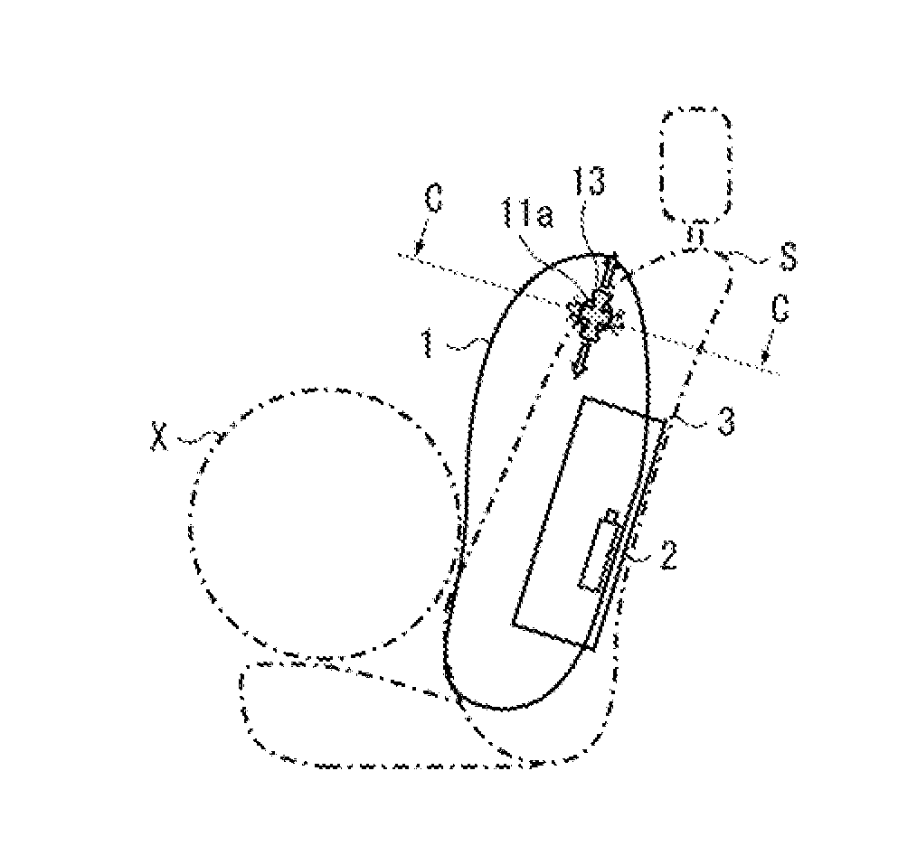
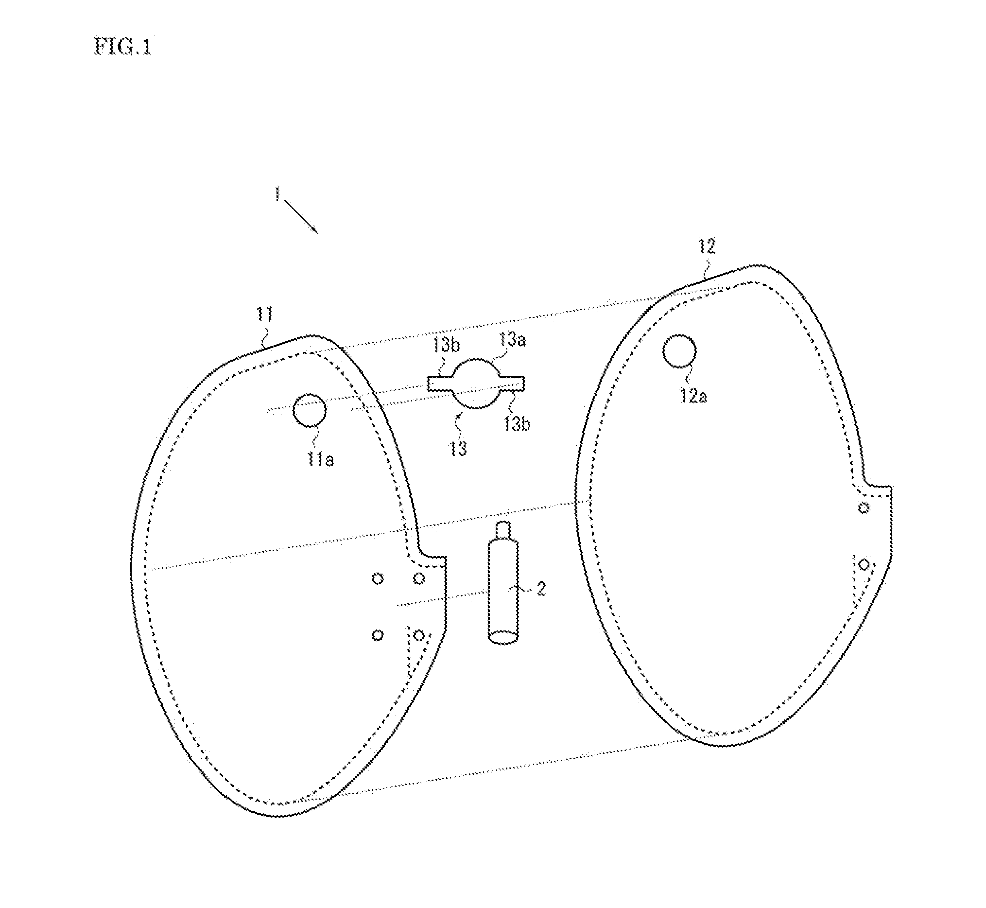
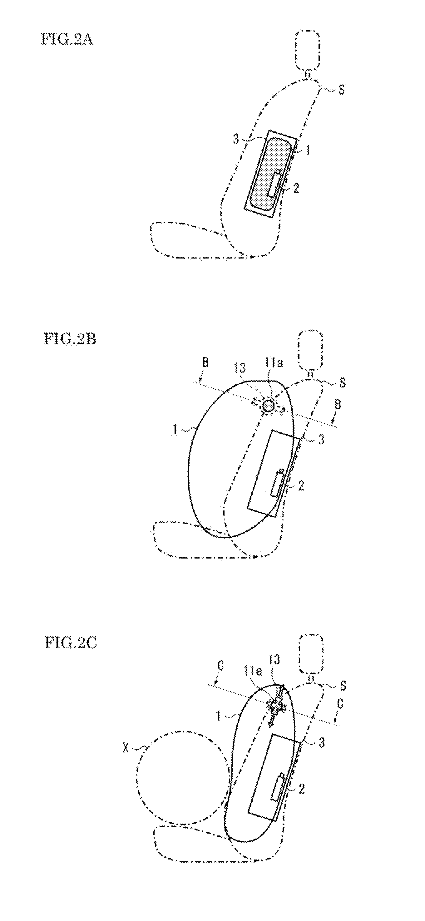
[0020]Referring now to FIGS. 1 to 4B, embodiments of the present invention are described below. FIG. 1 is an exploded view of components of an airbag device according to the present invention. FIGS. 2A to 2C illustrate stages of inflation / deployment of the airbag illustrated in FIG. 1 where FIG. 2A illustrates the airbag at a preceding stage of the inflation / deployment, FIG. 2B illustrates the airbag at a completion stage of the inflation / deployment, and FIG. 2C illustrates the airbag at an intermediate stage of the inflation / deployment. FIGS. 3A to 3D illustrate operations of a valve where FIG. 3A illustrates the valve in a closed state at the initial stage of the inflation / deployment, FIG. 3B illustrates the valve in the closed state at the completion stage of the inflation / deployment, FIG. 3C illustrates the valve in the open state at the intermediate stage of the inflation / deployment, and FIG. 3D illustrates a valve according to a modified example in the closed state at the init...

second embodiment

[0039]The airbag 1 illustrated in FIG. 4A has a slit (a cut) serving as the insertion hole 11a. This configuration can minimize a gap between the valve 13 and the insertion hole 11a, and thus can further reduce the leakage of gas.

third embodiment

[0040]The airbag 1 illustrated in FIG. 4B has a rectangular member serving as the valve 13. The rectangular member has a width larger than the diameter of the insertion hole 11a. This configuration can also function substantially similarly to the valve 13 having a wide portion 13a.

[0041]As illustrated in the second embodiment and the third embodiment, the shape of the insertion hole 11a or the valve 13 is appropriately changed depending on the conditions such as the type or the capacity of the airbag 1 or the location of the insertion hole 11a and is not limited to the one illustrated in the drawings.


PUM


Abstract

An airbag and an airbag device are provided that can effectively prevent a rise of the internal pressure of the airbag when the airbag is hindered from being normally inflated / deployed while gas is prevented from being wasted. An airbag includes a pair of side panels that form a bag by being sewn together, an insertion hole formed in the side panel, and a valve disposed on an inner side of the side panel so as to stop up the insertion hole and having two end portions connected to the side panel. While the airbag is housed in the structure, the valve is drawn to an outer side of the side panel through the insertion hole and disposed so as to stop up the insertion hole and, while the airbag is inflated / deployed, the valve is drawn to the inner side of the side panel.

Description

CROSS-REFERENCE TO RELATED APPLICATION[0001]This application claims priority under the Paris Convention to Japanese Application No. 2013-255623, filed Dec. 11, 2013, the contents of which are incorporated herein by reference in its entirety.FIELD OF THE INVENTION[0002]The present invention relates to airbags and airbag devices, and particularly, it relates to an airbag and an airbag device suitable as a side airbag that is inflated / deployed between an occupant and a door portion.BACKGROUND OF THE INVENTION[0003]Typical vehicles such as automobiles have increasingly been equipped with an airbag device to inflate / deploy an airbag inside the vehicle in an emergency such as at a collision of the vehicle so as to absorb an impact exerted on an occupant. Such an airbag device typically includes an airbag and an inflator that supplies gas to the airbag. The airbag is normally housed in a structure of the vehicle in a folded state whereas the airbag is inflated / deployed in an emergency.[000...

Claims


Application Information

Patent Timeline
IPC IPC(8): B60R21/231B60R21/207B60R21/26
CPCB60R21/23138B60R2021/23146B60R21/207B60R21/26B60R21/239B60R2021/2395
Inventor SHIBATA, DAISUKEHARAZUKA, KAZUHIROMIIDA, AKIKOSUGIMOTO, SHINICHI
Owner JOYSON SAFETY SYST JAPAN GK
Learn More