Rotating flow control diverter having dual stripper elements
Active Publication Date: 2015-06-11
WEATHERFORD TECH HLDG LLC
4 Cites 3 Cited by
AI-Extracted Technical Summary
Problems solved by technology
If the drill string continues to rotate, then the friction between the drill string and the stripper elements will wear and damage the stripper elements, and possibly cause them to fail.
Furthermore, pr...
Method used
[0028]The apparatus (10) of the present invention may be used for well control operations, to promote rig safety, to reduce the risk of environmental contamination, for underbalanced drilling operations, for managed pressure drilling operations and with conventional drilling operations.
[0031]It will be appreciated that if a torque is applied to the tubular about its axial direction, the friction between the upper and lower stripper elements (52, 82) and the tubular will be sufficient to transfer the torque to the upper and lower tubular shafts (50, 80), respectively. In turn, the upper and lower ...
Benefits of technology
[0008]In one embodiment of the apparatus, the housing comprises an upper portion of the housing a lower portion of the housing and a fastener. The upper portion of the housing defines an upper portion of the central bore. The upper sealed bearing assembly is mounted to the upper portion of the housing and supports the upper tubular shaft for axial rotation within the upper portion of the central bore. The lower portion of the housing defines the inlet and a lower portion of the central bore. The lower sealed bearing assembly is mounted to the lower portion of the housing and supports the lower tubular shaft for axial rotation within the lower portion of the central bore. The fastener removably secures the upper portio...
Abstract
The present invention is directed to rotating flow control diverter apparatus having an upper and a lower stripper element mounted on upper and lower tubular shaft, respectively, each of which is axially rotatable by means of an upper and lower sealed bearing assembly, respectively, within a central bore of a housing. An upper and lower seal assembly seal the annular space between the central bore and the upper and lower tubular shaft, respectively to define a purge chamber. The purge chamber is in fluid communication with the central bore via the lower tubular shaft, and may be provided with valved ports. The housing may be constructed in removably mounted upper and lower portions, to which the upper and lower sealed bearing assemblies, respectively, and upper and lower seal assemblies, respectively, are mounted.
Application Domain
Drilling rodsFluid removal +5
Technology Topic
EngineeringMechanical engineering
Image
Examples
- Experimental program(1)
Example
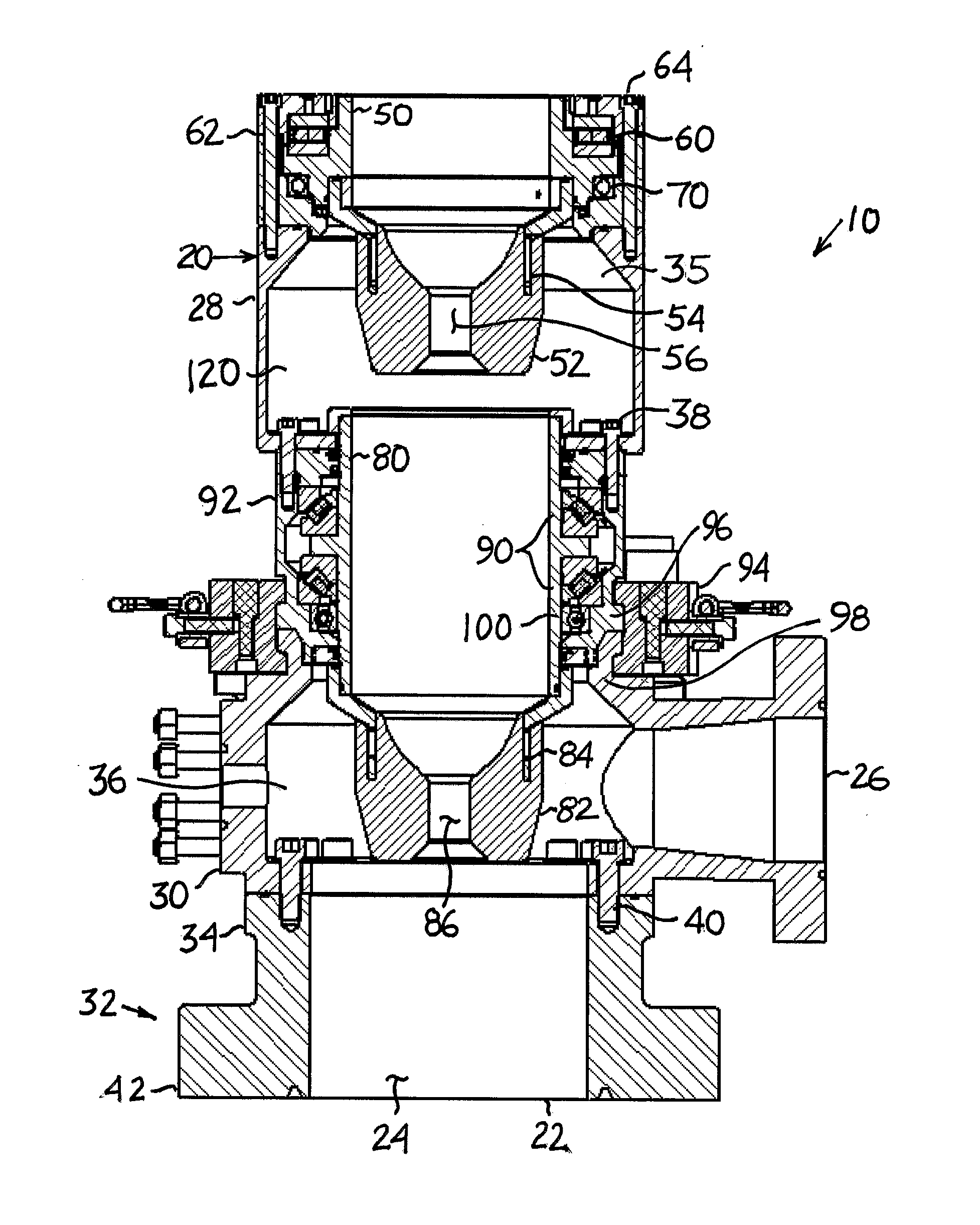
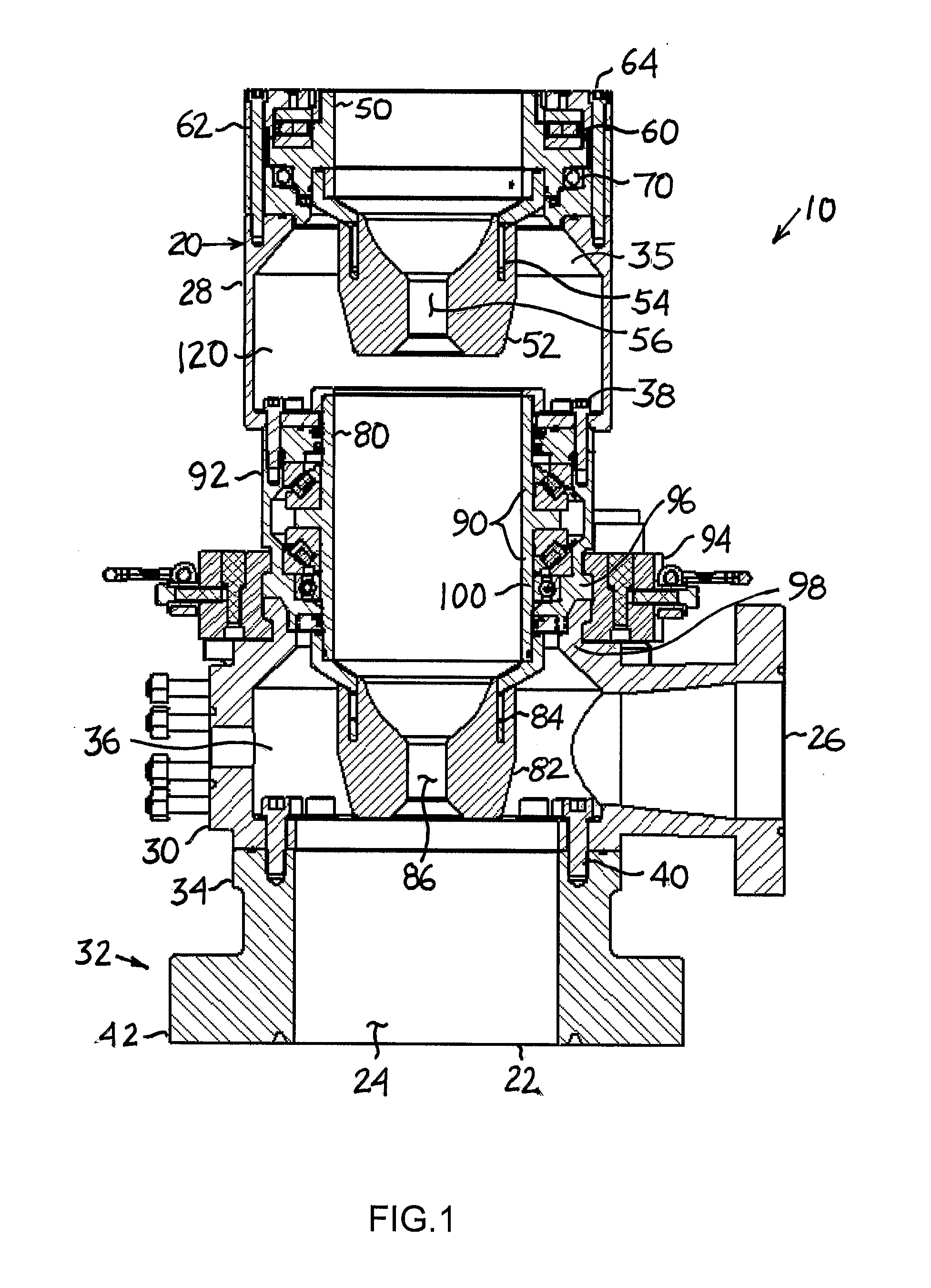
[0011]The invention relates to a rotating flow control diverter having dual stripper elements. When describing the present invention, all terms not defined herein have their common art-recognized meanings. To the extent that the following description is of a specific embodiment or a particular use of the invention, it is intended to be illustrative only, and not limiting of the claimed invention. The following description is intended to cover all alternatives, modifications and equivalents that are included in the spirit and scope of the invention, as defined in the appended claims.
[0012]As used herein, the term “well fluid” shall refer any liquid or gas, or combination thereof, that may emanate from a wellbore of an oil or gas well. Without limiting the generality of the foregoing, well fluids may include formation liquid or gas produced by the well, drilling fluid, and any gas that may be injected into the wellbore at the surface.
[0013]The present apparatus is directed to a rotating flow control diverter (10) having dual stripper elements, one embodiment of which is shown in FIG. 1. In general, the apparatus (10) comprises a housing (20), an upper tubular shaft (50), an upper stripper element (52), an upper sealed bearing assembly (60), an upper seal assembly (70), a lower tubular shaft (80), a lower stripper element (82), a lower sealed bearing assembly (90), and a lower seal assembly (100).
[0014]The housing (20) defines an inlet for well fluid (22) that is adapted for connection to the top of a wellhead or a blowout preventer stack. The housing (20) defines a central bore (24) in fluid communication with the inlet (22). The housing (20) further defines at least one outlet for well fluid (26) in communication with the central bore (24). The housing (20) may be made of any material that is sufficiently strong to withstand the operational pressures of well fluid to be expected within the housing; such materials may include, without limitation, 41/30 alloy steel.
[0015]In one embodiment not shown, the entirety of the housing (20) may be monolithically constructed, and may include a flanged connection for connection to other wellhead components such as a blow out preventer.
[0016]In one embodiment as shown in FIG. 1, the housing (20) comprises an upper portion of the housing (28), a lower portion of the housing (30) and a flanged connection (32). The upper portion of the housing (28) and the lower portion of the housing (30) define an upper portion of the central bore (35) and a lower portion of the central bore (36), respectively. The upper portion of the housing (28) is removably attached to the lower portion of the housing (30) with a fastener, such as but not limited to bolts (38) passing through bolt holes tapped into the body of the lower portion of the housing (28). The lower portion of the housing (30) is removably attached to the flanged connection (32) with a fastener, such as but not limited to bolts (40) passing through the bolt holes tapped into the body of the flanged connection (32). Gaskets or a-ring seals (not shown) may be provided between the upper portion of the housing (28) and the lower portion of the housing (30), and between the lower portion of the housing (30) and the flanged connection (32) to provide a fluid-tight seal between the interfacing parts. In the embodiment shown in FIG. 1, the flanged connection (32) is a double flanged steel spool. The upper flange (34) of the spool is adapted to mate with the bottom end of the lower portion of the housing (30). As such, the upper flange (34) should be selected to match the working pressure, custom profile and integrity of the lower portion of the housing (30). The integrally machined lower flange (42) of the spool is adapted to mate with the top of a wellhead or the blowout preventer. In one embodiment, the lower flange (42) may conform to a standard flange specification of the American Petroleum Institute (API). For example, the lower flange (42) may be a 13⅝″ 5000 PSI API flange. The use of such a double flanged spool, allows the lower portion of the housing (30) to be a standardized component that can adapted to receive well fluid from a variety of different wellheads or blowout preventer stacks.
[0017]The upper tubular shaft (50) is proportioned to allow a tubular (such as a drill string) to pass through in the axial direction. The upper tubular shaft (50) has an attached upper stripper element (52) that, in use, establishes a fluid-tight seal between the upper tubular shaft (50) and the outer surface of a tubular passing through it. The upper tubular shaft (50) may be made of any suitably strong and rigid material such as alloy steel, and the upper stripper element (52) may be made of an elastomeric material.
[0018]In one embodiment as shown in FIG. 1, the upper stripper element (52) is attached to the lower end of the upper tubular shaft (50) by means of an insert (54) attached to the outer surface of upper tubular shaft (50) and extending into the body of the upper stripper element (52). The upper stripper element (52) has a frustum shape with the narrow end oriented downwards. The upper stripper element (52) defines a passage (56) having a diameter that is slightly smaller than the outer diameter of a tubular to be passed through upper tubular shaft (50). The foregoing description of one embodiment of the upper stripper element (52) and the manner of its attachment to the upper tubular shaft (50) is not intended to be limiting of the claimed invention, and one skilled in the art will recognize that any suitable stripper elements may be employed with the apparatus (10).
[0019]The upper sealed bearing assembly (60) supports the upper tubular shaft (50) for axial rotation within the central bore (24). One skilled in the art will recognize that any suitable sealed bearing assembly may be employed as the upper bearing assembly (60) in the apparatus (10).
[0020]In one embodiment as shown in FIG. 1, the upper sealed bearing assembly (60) is mounted within a removably attachable sub-assembly (62) of the housing (20). The sub-assembly is removably secured to remaining portion of the housing (20) with a fastener, such as but not limited to bolts (64) passing through bolt holes formed in the body of the housing (20).
[0021]The upper seal assembly (70) seals the annular space between the central bore (24) and the outside surface of the upper tubular shaft (50), thereby preventing well fluid from passing between these two parts. In one embodiment as shown in FIG. 1, the upper seal assembly (70) is provided in the form of an O-ring which is installed as part of the sub-assembly (62) of the housing (20) that supports the upper sealed bearing assembly (60). One skilled in the art will appreciate that the upper seal assembly (70) may be implemented by other suitable means known in the art.
[0022]The lower tubular shaft (80) is proportioned to allow a tubular (such as a drill string) to pass through in the axial direction, and is axially aligned with the upper tubular shaft (50). The lower tubular shaft (80) has an attached lower stripper element (20) that, in use, establishes a fluid-tight seal between the lower tubular shaft (80) and the outer surface of a tubular passing through it. The lower tubular shaft (80) may be made of any suitably strong and rigid material such as alloy steel, and the lower stripper element (82) may be made of an elastomeric material.
[0023]In one embodiment as shown in FIG. 1, the lower stripper element (82) is attached to the lower end of the lower tubular shaft (80) by means of an insert (84) attached to the outer surface of lower tubular shaft (80) and extending into the body of the lower stripper element (82). The lower stripper element (82) may be different, similar or identical to the upper stripper element (52).
[0024]The lower sealed bearing assembly (90) supports the lower tubular shaft (80) for axial rotation within the central bore (24) of the housing. One skilled in the art will recognize that any suitable sealed bearing assembly may be employed as the lower bearing assembly (90) in the apparatus (10).
[0025]In one embodiment as shown in FIG. 1, the lower sealed bearing assembly (90) is mounted within a removably attached sub-assembly (92) of the lower portion of the housing (20). The sub-assembly (92) is removably secured to the remaining portion of the housing (20) by a fastener, such as but not limited to a clamp (94) that binds a flange (96) on the lower end of the sub-assembly against a complementary flange (98) on the upper end of the lower portion of the housing (20). In one embodiment, the clamp (94) is a solid locking ring clamp with complementary locking tabs. The clamp (94) may be either manually or hydraulically actuated.
[0026]The lower seal assembly (100) seals the annular space between the central bore (24) and the outside surface of the lower tubular shaft (80), thereby preventing well fluid from passing between these two parts. In one embodiment as shown in FIG. 1, the lower seal assembly (100) is provided in the form of an O-ring which is installed as part of the sub-assembly (92) of the housing (20) that supports the lower sealed bearing assembly (90). One skilled in the art will appreciate that the lower seal assembly (100) may be implemented by other suitable means known in the art.
[0027]In one embodiment as shown in FIG. 1, the apparatus (10) has a purge chamber (120) defined by a section of the central bore (24) between the upper seal assembly (70) and the lower seal assembly (100). The purge chamber (120) is in fluid communication with the portion of the central bore (24) below the lower seals assembly (100) via the lower tubular shaft (80). In one embodiment, the housing (20) may define at least one valved port (not shown) in fluid communication with the purge chamber (120). In one embodiment, the apparatus (10) may further comprise a means for monitoring fluid pressure (not shown) within the purge chamber (120) such as a pressure gauge or a pressure-sensitive transducer.
[0028]The apparatus (10) of the present invention may be used for well control operations, to promote rig safety, to reduce the risk of environmental contamination, for underbalanced drilling operations, for managed pressure drilling operations and with conventional drilling operations.
[0029]The use and operation of the apparatus (10) in the embodiment shown in FIG. 1 is now described by way of a non-limiting example. The apparatus (10) is installed on the top of a blowout preventer stack by bolts passing through bolt holes (not shown) in the lower flange (42) of the flanged connection (32). The removable attachment of the upper portion of the housing (28) to the lower portion of the housing (30), and the removable attachment of the lower portion of the housing (30) to the flanged connection (32) allows the apparatus (10) to be installed either selectively in stages, or as a single pre-assembled unit, and to be selectively dismantled in stages such as for servicing internal components.
[0030]A tubular is inserted downwardly through the upper tubular shaft (50) and subsequently through the lower tubular shaft (80). As the diameter of the passage (56) of the upper stripper element (52) and the passage (86) of the lower stripper element (82) are slightly smaller than the outer diameter of the tubular inserted, the upper stripper element (52) and the lower stripper element (82) will stretch fit around the tubular, providing a seal around the tubular.
[0031]It will be appreciated that if a torque is applied to the tubular about its axial direction, the friction between the upper and lower stripper elements (52, 82) and the tubular will be sufficient to transfer the torque to the upper and lower tubular shafts (50, 80), respectively. In turn, the upper and lower tubular shafts (50, 80) will rotate within the housing (20), as permitted by the upper and lower sealed bearing assemblies (60, 90). The provision of two distinct and independent sealed bearing assemblies (60, 90) for each of the tubular shafts (50, 80) is advantageous in that the failure of either one of the sealed bearing assemblies (60, 90) prevents only one, and not both, of the tubular shafts (50, 80) from rotating. The stripper element (52, 82) that is attached to the still rotatable tubular shaft (50, 80) is thereby protected from excessive wear or damage if the tubular continues to rotate.
[0032]Well fluid flowing upwardly through the top of the blowout preventer flows through the inlet (22) into the lower portion of the central bore (24). The pressure of the well fluid acts upwardly on the lower, narrow end of the frustum-shaped lower stripping element (82), thereby urging it into further sealing relationship with the tubular. The lower seal assembly (100) prevents the well fluid from flowing further upwards within the central bore, thereby containing the well fluid. The outlet (26) may be selectively opened to divert the upward flowing well fluid away from the rig floor, through an alternative flow line.
[0033]Under normal operating conditions, the lower stripper element (82) prevents the upwardly flowing well fluid from flowing upwardly through the lower tubular shaft (80). If, however, the pressure of the upward flow well fluid is sufficiently high, or if either the lower stripper element (82) or the lower seal assembly (100) becomes worn or damaged, them the well fluid may leak either between the lower stripper element (82) and the tubular passing through the inside of the lower tubular shaft (80), or between the lower portion of the housing (30) and the outside surface lower tubular shaft (80), and upwards into the purge chamber (120).
[0034]If a fluid pressure monitor or sensor in the purge chamber (120) is provided, an operator may use this information to monitor the wear of the lower stripper element (82) and the lower seal assembly (100) and, thus forecast a failure either of these seals before a failure occurs, and schedule suitable maintenance or repair procedures.
[0035]If valved ports in fluid communication with the purge chamber (120) are provided, the operator may use the valved ports to introduce any suitable inert gas into one of the valved ports while allowing trapped well fluids to escape from the purge chamber through another valved port. For example, in sour gas drilling, small amounts of sour gases and liquids may be trapped in tool joint grooves of the tubular as it passes through the lower stripper element (82). Inert gas such as nitrogen can be introduced into the purge chamber using one of the valved ports, while allowing sour gases to vent out of the purge chamber through another valved port. The vented sour gases can be captured and diverted from the rig floor.
[0036]As will be apparent to those skilled in the art, various modifications, adaptations and variations of the foregoing specific disclosure can be made without departing from the scope of the invention claimed herein.
PUM


Description & Claims & Application Information
We can also present the details of the Description, Claims and Application information to help users get a comprehensive understanding of the technical details of the patent, such as background art, summary of invention, brief description of drawings, description of embodiments, and other original content. On the other hand, users can also determine the specific scope of protection of the technology through the list of claims; as well as understand the changes in the life cycle of the technology with the presentation of the patent timeline. Login to view more.