Supercharge Your Innovation With Domain-Expert AI Agents!

Hazardous location heat transfer unit

a heat transfer unit and hazardous location technology, applied in the field can solve the problems of localized atmospheric chemicals, affecting the efficiency of heat transfer units,

Active Publication Date: 2015-06-11
KOOLTRONIC
View PDF7 Cites 0 Cited by
  • Summary
  • Abstract
  • Description
  • Claims
  • Application Information

AI Technical Summary

Problems solved by technology

Such environments can pose a hazard because most conventional air conditioning or heat exchanger units contain components that have elements which should not be exposed to the hazardous environment, for example, motors, switches and relays, because they have the potential to create sparks or have one or more sufficiently hot surfaces that can interact with the dust or vapor to cause an explosion or ignition.
Likewise, those sparks and / or hot surfaces can cause localized atmospheric chemicals to react with and quickly degrade components of the units themselves.
All such approaches however increase cost and complexity of the units.

Method used


Image

  • Hazardous location heat transfer unit
  • Hazardous location heat transfer unit
  • Hazardous location heat transfer unit

Examples


Embodiment Construction

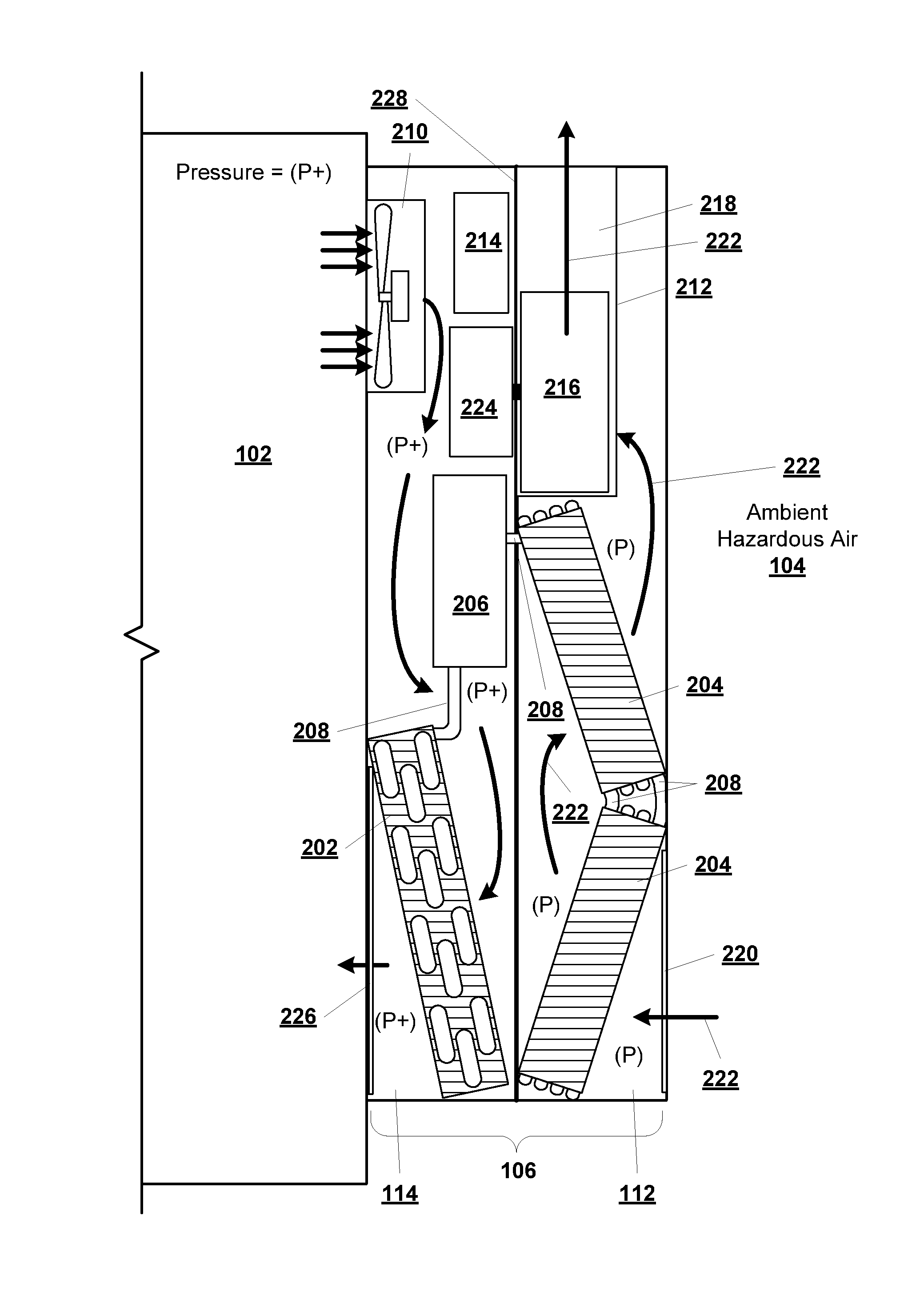
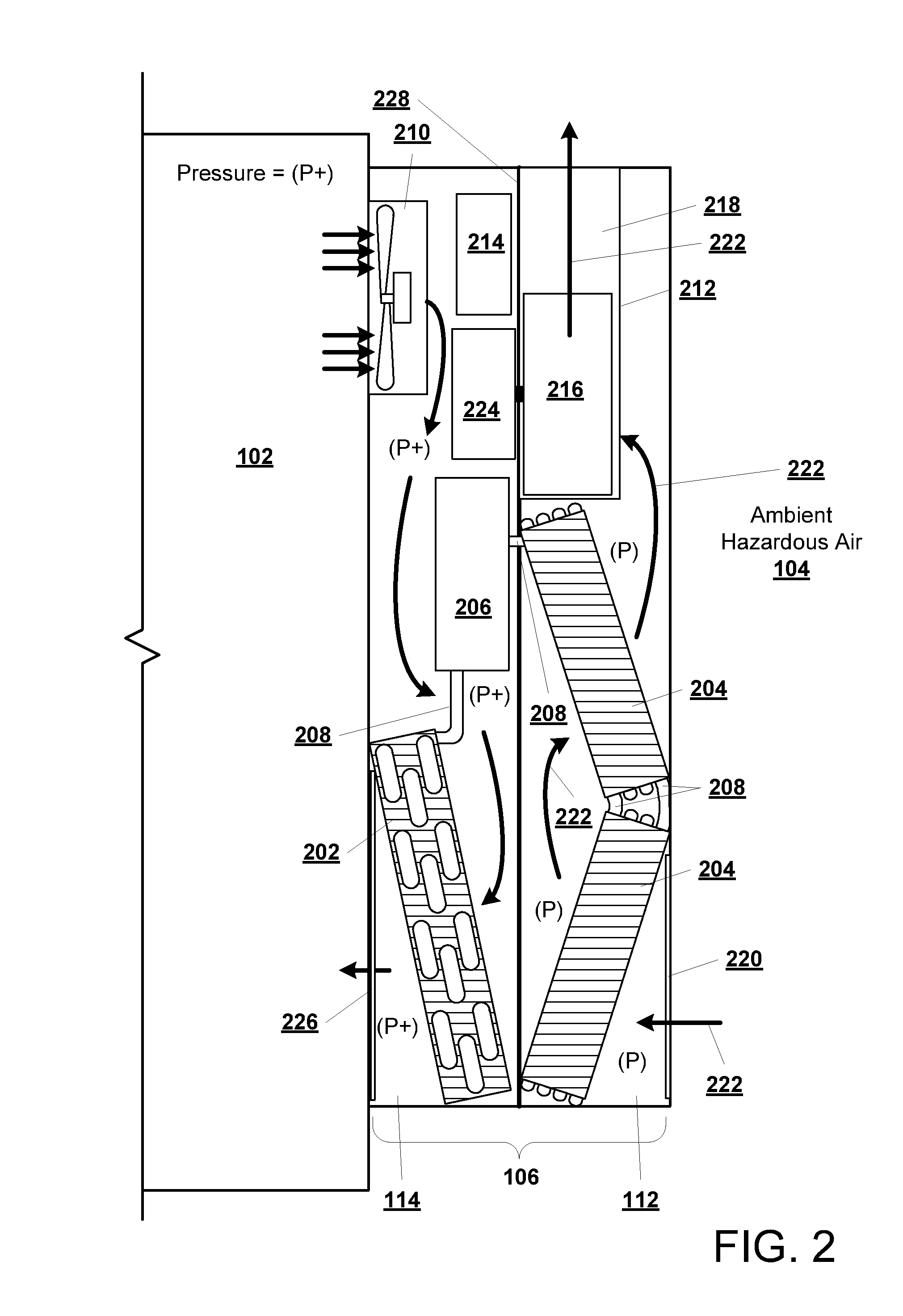
[0024]Before describing the details of the devices and approaches herein, it should be understood that, as used herein, the term “hazardous location” is intended to broadly mean any location (irrespective of geographic location) meeting the National Electrical Code definition of a “Class I, Division 1” location where materials in one or more of Groups A, B, C and / or D are present, and / or meeting the definition of that Code corresponding to a “Class II, Division 1” location where materials in one or more of Groups D, E and / or F are present.

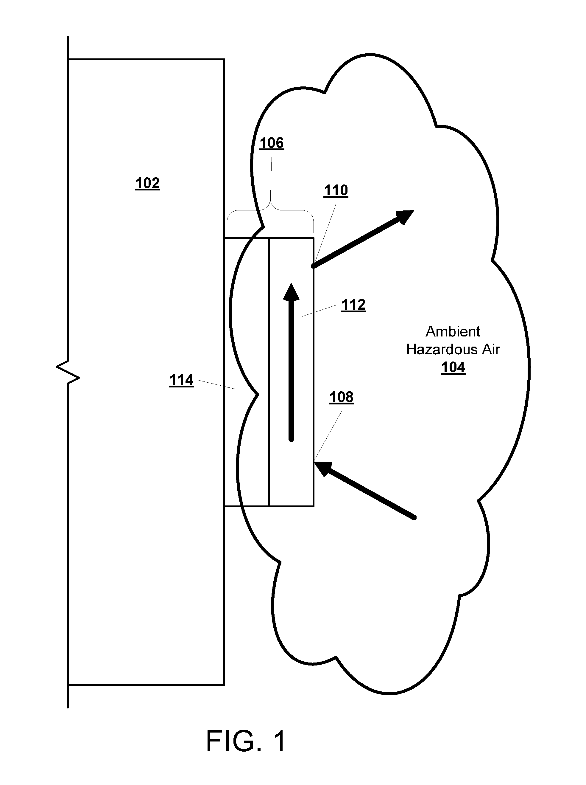
[0025]In addition, as used herein, the term “hazardous air” is intended to mean and encompass air in which flammable gases or vapors may be present in sufficient quantities to be explosive or ignitable, or air containing combustible dust or fiber in sufficient quantities so as to be explosive or ignitable such that the location where the hazardous air is present will be a hazardous location as defined herein.

[0026]Finally, as used herein, the term ...


PUM

PropertyMeasurementUnit
internal pressureaaaaaaaaaa
heataaaaaaaaaa
flammableaaaaaaaaaa

Abstract

A two chamber heat transfer unit configured such that hazardous air can circulate through one of the chambers and potential ignition source components are contained in another chamber through which the gas to be heated or cooled will circulate.

Description

CROSS REFERENCE TO RELATED APPLICATION[0001]This application is a divisional of U.S. patent application Ser. No. 14 / 521,224, filed Oct. 22, 2014, which claims the priority benefit of U.S. Provisional Patent Application No. 61 / 895,836, filed Oct. 25, 2013, both of which are incorporated herein by reference in their entireties as if fully set forth herein.BACKGROUND[0002]1.Field[0003]This disclosure relates generally to heat transfer units, like air conditioners and heat exchangers, and, more particularly, to heat transfer units used in hazardous environments.[0004]2. Background[0005]In industrial applications, it is not uncommon to have locations where cooling or heat transfer from a location or housing is needed, yet the ambient atmosphere in the area to which the heat will be transferred contains fine dust or flammable vapor or chemicals which, when subjected to high heat or localized arcing, become overly corrosive (such locations being individually and collectively referred to he...

Claims


Application Information

Patent Timeline
Patent Type & Authority Applications(United States)
IPC IPC(8): F25B49/00
CPCF25B49/005F28D15/0266F28F2265/00Y10T29/49826H05K7/20609H05K7/206B23P19/04H05K7/20554F24F13/20F25B2500/06
Inventor KREELEY, BRUCE K.MUZIKANT, BORIS L.
Owner KOOLTRONIC
Features
  • R&D
  • Intellectual Property
  • Life Sciences
  • Materials
  • Tech Scout
  • Unparalleled Data Quality
  • Higher Quality Content
  • 60% Fewer Hallucinations
Learn More