
Clot retrieval device for removing occlusive clot from a blood vessel

a technology of clot retrieval and blood vessel, which is applied in the field of removing acute obstructions from blood vessels, can solve the problems of high performance, difficult to position guide catheters, and difficult to deliver devices, so as to reduce the risk of reperfusion injury, reduce the pressure gradient across the clot, and facilitate the removal of the clot

Active Publication Date: 2015-06-18
NEURAVI
View PDF13 Cites 109 Cited by
  • Summary
  • Abstract
  • Description
  • Claims
  • Application Information

AI Technical Summary

Benefits of technology

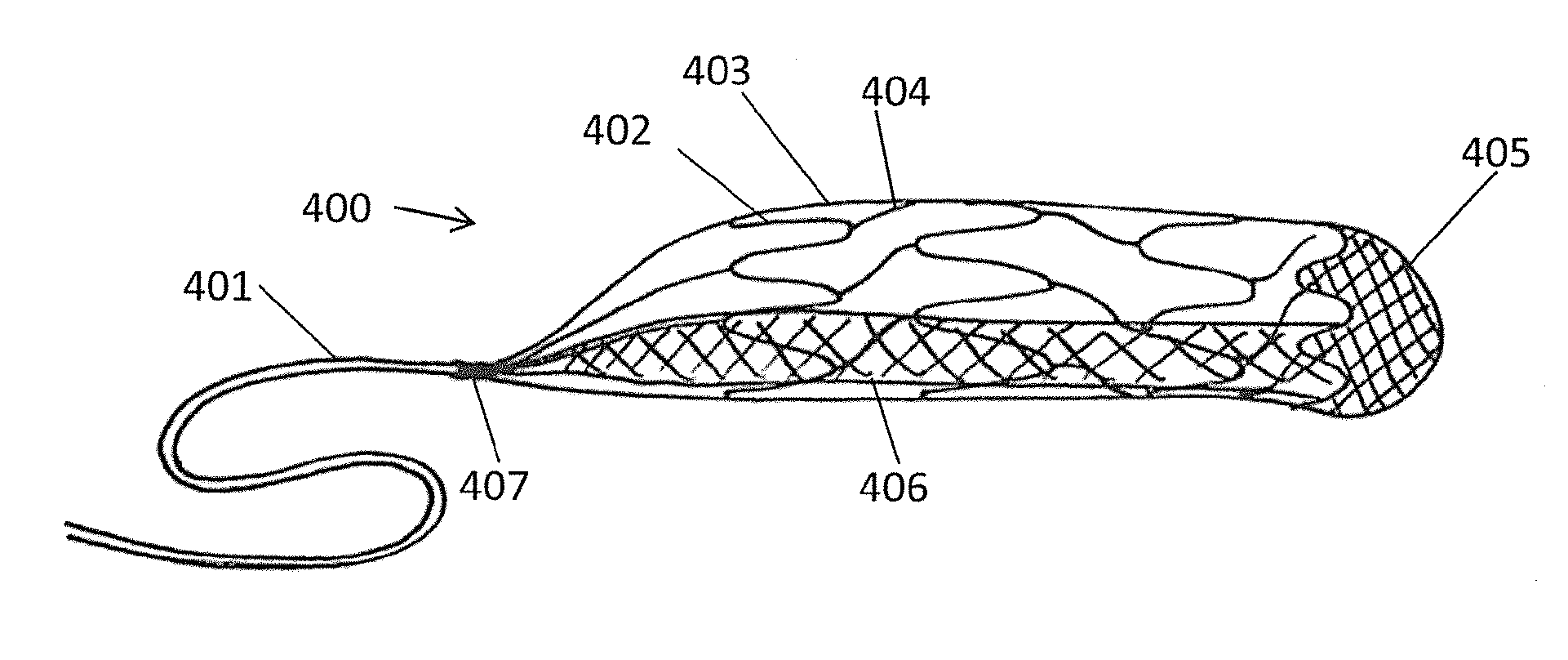
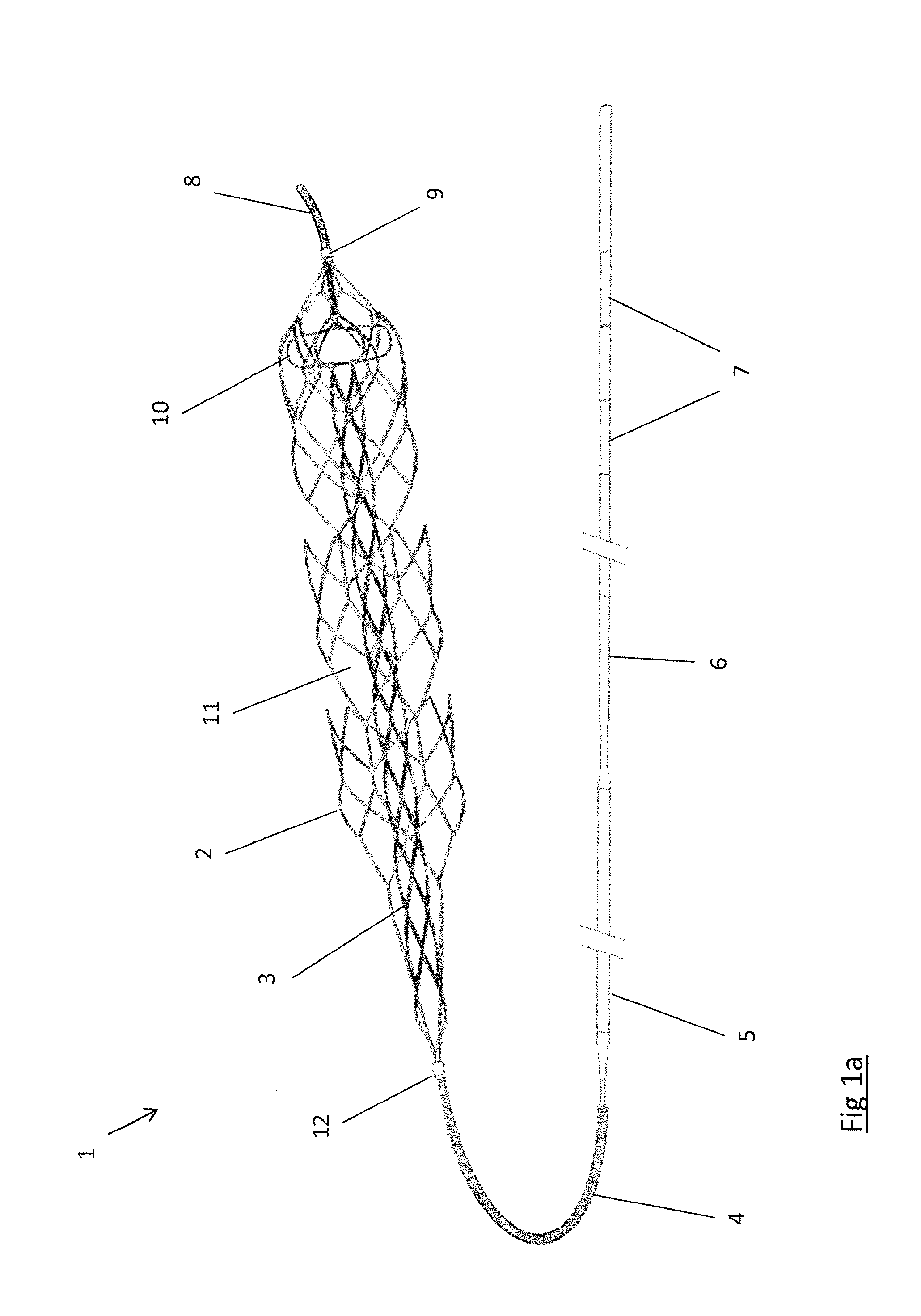
[0022]the distal portion of the inner elongate member and the distal end portion of the outer elongate body together defining a three dimensional protective structure to substantially prevent distal egress of clot or clot fragments from the device.
[0036]Designs are disclosed in which a clot engaging portion of the device is configured to be expanded within an occlusive clot in a blood vessel so that the expanding engager allows the clot to migrate into a reception space within the body of the engager as the engager expands. The engager is delivered through a catheter to the site of the occlusion and is positioned within the clot. The engager is expandable at the site of the occlusion and starts to compress the clot as it is expanded. The engager surface comprises inlet openings and the inlet openings allow the clot to ‘escape’ from compression by displacing a significant portion of the clot through the inlet openings in the wall of the engager. Because a significant portion of the clot is urged through the inlet openings in the engager this minimizes compression of the clot and hence minimizes the resultant increase in the clot coefficient of friction. This also reduces the radial force on the vessel in the region of the clot which means a lesser force is required to withdraw the captured clot, which in turn means less vessel trauma and less tension on the distal vascular bed. The device is configured such that the radial force of the device acts strongly at a small diameter to engage with and grip clot, but acts softly at a larger diameter to gently contact the vessel wall are also disclosed.
[0038]These dual expandable member devices have a number of benefits. (1) The inner member can be configured to provide a strong opening force to create a lumen through the clot and restore flow immediately on deployment. This flow lumen reduces the pressure gradient across the clot, making it easier to remove the clot. (2) The diameter to which the inner member expands may be tailored so as to reduce the risk of a reperfusion injury. With this embodiment the inner member expands to a diameter that is significantly smaller than the diameter of the vessel immediately adjacent to and distal of the occlusion. This small diameter inner member creates a small flow lumen across the occlusion and restricts the initial blood flow to the affected portion of the brain. This restricted blood flow ensures that the pressure applied to blood vessels immediately after flow restoration is lower than normal and this reduces the risk of bleeding in the ischemic vascular bed. Full perfusion is subsequently restored by removing the device and the clot. (3) The inner member may be configured to expand to a lesser diameter than the outer basket and to a lesser diameter than any vessel in which it is to be deployed. This means that a strong radial force may be safely exerted on the clot to open up a flow lumen, but need not be exerted on the vessel. (4) The inner member can serve to scaffold the lumen created through the clot, preventing the liberation of emboli from the clot into the resultant fast flowing bloodstream. (5) The inner member may at least partially comprise a stent and can provide a strong grip on the clot for the critical initial step of disengaging the clot from the vessel, enabling the outer basket to be configured with a low radial force. (6) The outer member may be configured to have large inlet openings so as to urge clot across the wall of the outer. The inner member on the other hand may be configured to prevent distal migration or fragmentation or embolization of clot that traverses the wall of the outer member. By configuring the outer member so as to encourage clot to traverse the wall of the outer member the device can more effectively disengage clot from the wall of the vessel while the device is also effective at preventing loss of clot material with an inner member with a shape and substructure that provides scaffolding.
[0039]Designs are also disclosed which further reduce this embolization risk by providing a distal net or scaffolding zone across the vessel lumen towards the distal end of the device. This scaffolding may be appended to either the inner or outer member or to both members, and may be three dimensional in that it has depth as well as surface area. Combining the scaffolding of both inner and outer members may provide a more effective filter than utilizing one member alone. Designs are disclosed utilising fibres or fine wires to provide added scaffolding with minimal impact on device profile or deliverability.
[0040]Designs are disclosed of devices with long and highly flexible inner members which may extend significantly proximally of the outer member, enabling the device to be used to retrieve particularly long clots. The small diameter and flexible inner member expands to provide a flow lumen through the clot (reducing the pressure gradient and making the clot easier to remove) but does not expand to the diameter of the vessel in which it is deployed. Thus the resultant device can be delivered and retrieved more safely (at much lower forces) than a similar length device whose diameter was configured to engage with the vessel over its entire length.

Problems solved by technology

Acute obstructions may include clot, misplaced devices, migrated devices, large emboli and the like.
There are significant challenges associated with designing clot removal devices that can deliver high levels of performance:
There are a number of access challenges that make it difficult to deliver devices.
In cases where access involves navigating the aortic arch (such as coronary or cerebral blockages) the configuration of the arch in some patients makes it difficult to position a guide catheter.
The tortuosity challenge is even more severe in the arteries approaching the brain.
The right ventricular outflow tract and pulmonary arteries are delicate vessels that can easily be damaged by inflexible or high profile devices.
The vasculature in the area in which the clot may be lodged is often fragile and delicate.
Excessive tensile forces applied on these vessels could result in perforations and hemorrhage.
Pulmonary vessels are larger than those of the cerebral vasculature, but are also delicate in nature, particularly those more distal vessels.
Long strands of softer clot material may tend to lodge at bifurcations or trifurcations, resulting in multiple vessels being simultaneously occluded over significant lengths.
In particular compression of blood clot causes dehydration of the clot and results in a dramatic increase in both clot stiffness and coefficient of friction.
If the RF is too low the stent-like clot retriever will lose its grip on the clot, but if the RF is too high the stent-like clot retriever may damage the vessel wall and may require too much force to withdraw.
Therefore stent-like clot retrievers that have sufficient radial force to deal with all clot types may cause vessel trauma and serious patient injury, and stent-like clot retrievers that have appropriate radial force to remain atraumatic may not be able to effectively handle all clot types.
This compressive force will tend to dehydrate the clot, which in turn tends to increase its coefficient of friction, making it more difficult to remove from the vessel.
Conventional Stent-like clot retriever designs do not retain their expanded shape very well when placed in tension in bends, due to the manner in which their strut elements are connected to one another.
This can result in a loss of grip on a clot as the stent-like clot retriever is withdrawn proximally around a bend in a tortuous vessel, with the potential escape of the captured clot.
Another disadvantage with this approach is that it relies on pinning the clot between the stent-like clot retriever and the vessel wall and thus may not restrain the clot effectively when passing a branch vessel or when passing into a vessel that is larger than the fully expanded diameter of the stent-like clot retriever.
Pinning the clot between the stent-like clot retriever and the vessel wall in order to remove it from the vessel also results in high shear forces against the side of the clot as it is removed, potentially releasing fragments of the clot.
If these fragments are not retained by the device they may be released leading to further blockages in the distal vasculature.
A particular difficulty encountered when attempting to remove long clots is that conventional devices may be shorter than the clot itself.
A device that is shorter than the clot is unlikely to be able to restore flow through the occluded area upon deployment, and thus the pressure gradient across the clot remains a significant impediment to its removal.
Simply making such a device longer would likely render it difficult to track through tortuous anatomies and could be traumatic to the vasculature, taking more force to withdraw and potentially getting stuck and requiring surgery to remove.
However each time a clot retrieval device is withdrawn the access to the target site is lost.
Navigating the guidewire and microcatheter to the clot can take a considerable amount of time especially if the vessels are tortuous.
This additional time and device manipulation all adds to the risks to which the patient is exposed.
Existing devices do not adequately address these challenges.

Method used


Image

  • Clot retrieval device for removing occlusive clot from a blood vessel
  • Clot retrieval device for removing occlusive clot from a blood vessel
  • Clot retrieval device for removing occlusive clot from a blood vessel

Examples


Embodiment Construction

[0215]Specific embodiments of the present invention are now described in detail with reference to the figures, wherein identical reference numbers indicate identical or functionality similar elements. The terms “distal” or “proximal” are used in the following description with respect to a position or direction relative to the treating physician. “Distal” or “distally” are a position distant from or in a direction away from the physician. “Proximal” or “proximally” or “proximate” are a position near or in a direction toward the physician.

[0216]Accessing cerebral, coronary and pulmonary vessels involves the use of a number of commercially available products and conventional procedural steps. Access products such as guidewires, guide catheters, angiographic catheters and microcatheters are described elsewhere and are regularly used in cath lab procedures. It is assumed in the descriptions below that these products and methods are employed in conjunction with the device and methods of t...


PUM


Abstract

A clot retrieval device 1 for removing occlusive clot from a blood vessel, the device comprises an inner elongate body 3 having a collapsed delivery configuration and an expanded deployed configuration and an outer elongate body 2 at least partially overlying the inner elongate body 2. The outer elongate body 2 is expandable to a radial extent which is greater than the radial extent of the inner body 3 in the deployed configuration to define a clot reception space 11. The outer elongate body 2 comprises a distal end portion 24,49 and the inner elongate body 3 comprises a main body portion 10 and a distal portion which extends in the deployed configuration towards the outer elongate body 2 to a greater extent than the main body portion. The distal portion 10 of the inner elongate member 3 and the distal end portion 24,49 of the outer elongate body 2 together define a three dimensional protective structure to substantially prevent distal egress of clot or clot fragments from the device.

Description

FIELD OF THE INVENTION [0001]This invention relates to devices and methods of removing acute blockages from blood vessels. The invention especially relates to removing acute obstructions from blood vessels. Acute obstructions may include clot, misplaced devices, migrated devices, large emboli and the like. Thromboembolism occurs when part or all of a thrombus breaks away from the blood vessel wall. This clot (now called an embolus) is then carried in the direction of blood flow. An ischemic stroke may result if the clot lodges in the cerebral vasculature. A pulmonary embolism may result if the clot originates in the venous system or in the right side of the heart and lodges in a pulmonary artery or branch thereof. Clots may also develop and block vessels locally without being released in the form of an embolus—this mechanism is common in the formation of coronary blockages. The invention is particularly suited to removing clot from cerebral arteries in patients suffering acute ische...

Claims


Application Information

Patent Timeline
Patent Type & Authority Applications(United States)
IPC IPC(8): A61B17/221
CPCA61B17/221A61F2/013A61B17/320725A61B2017/22034A61B2017/2212A61B2017/2215A61B17/12109A61B2017/00358A61B2017/00778A61M29/00
Inventor BRADY, EAMONCASEY, BRENDANGILVARRY, MICHAELHARDIMAN, DAVIDMCARDLE, KEVINRAZAVI, MAHMOODVALE, DAVID
Owner NEURAVI
Learn More