Hydraulic system for a knee-ankle assembly controlled by a microprocessor

a microprocessor and articulation system technology, applied in the field of knee and ankle prosthesis, can solve the problems of “falling” on the contralateral limb, significant increase in the effort taken by, and increase in the joint torque in the entire contralateral limb

Active Publication Date: 2015-07-02
PROTEOR
View PDF19 Cites 26 Cited by
  • Summary
  • Abstract
  • Description
  • Claims
  • Application Information

AI Technical Summary

Benefits of technology

[0023]One of the purposes of the invention is to thus provide a solution for these disadvantages by offering a knee-ankle prosthesis of a simple and non-cumbersome design, which will allow reproducing the movements made by bi-articular muscles such as the gastrocnemius.
[0032]The flexion of the knee allows a dorsiflexion of the ankle in proportion to the movement of the knee during the stance phase and the flexion of the knee results in dorsiflexion of the ankle during the swing phase.

Problems solved by technology

This results in a “fall” on the contralateral limb and a significant increase in the effort taken by it.
This effort results in an increase in the joint torques in the entire contralateral limb.
It will be noted that, even though the motor works only during the swing phase, it is already very large, noisy and consumes a lot of energy since it is the motor that allows moving the leg in the swing phase in each step.
Moreover, the motor is likely to be noisy.
However, mobility in dorsiflexion is limited)(3°.
However, such a solution appears to be limited owing to reasons of space requirement.
The functions executed are thus more important than the Elan®, marketed by Endolite, but the valve is continuously controlled, which consumes a high amount of energy.
This strategy expends a lot of energy (elevation of the center of mass) and results in twisting of the pelvis and the lower back.
Moreover, this prosthesis, which was designed in the 1940s, does not include any mechatronics and thus cannot adapt to different walking situations.

Method used


Image

  • Hydraulic system for a knee-ankle assembly controlled by a microprocessor
  • Hydraulic system for a knee-ankle assembly controlled by a microprocessor
  • Hydraulic system for a knee-ankle assembly controlled by a microprocessor

Examples


Embodiment Construction

[0052]In order to make things clearer, in the following description, the same elements have been referred to by the same references in the various figures. Moreover, the various cross sections are not drawn to scale.

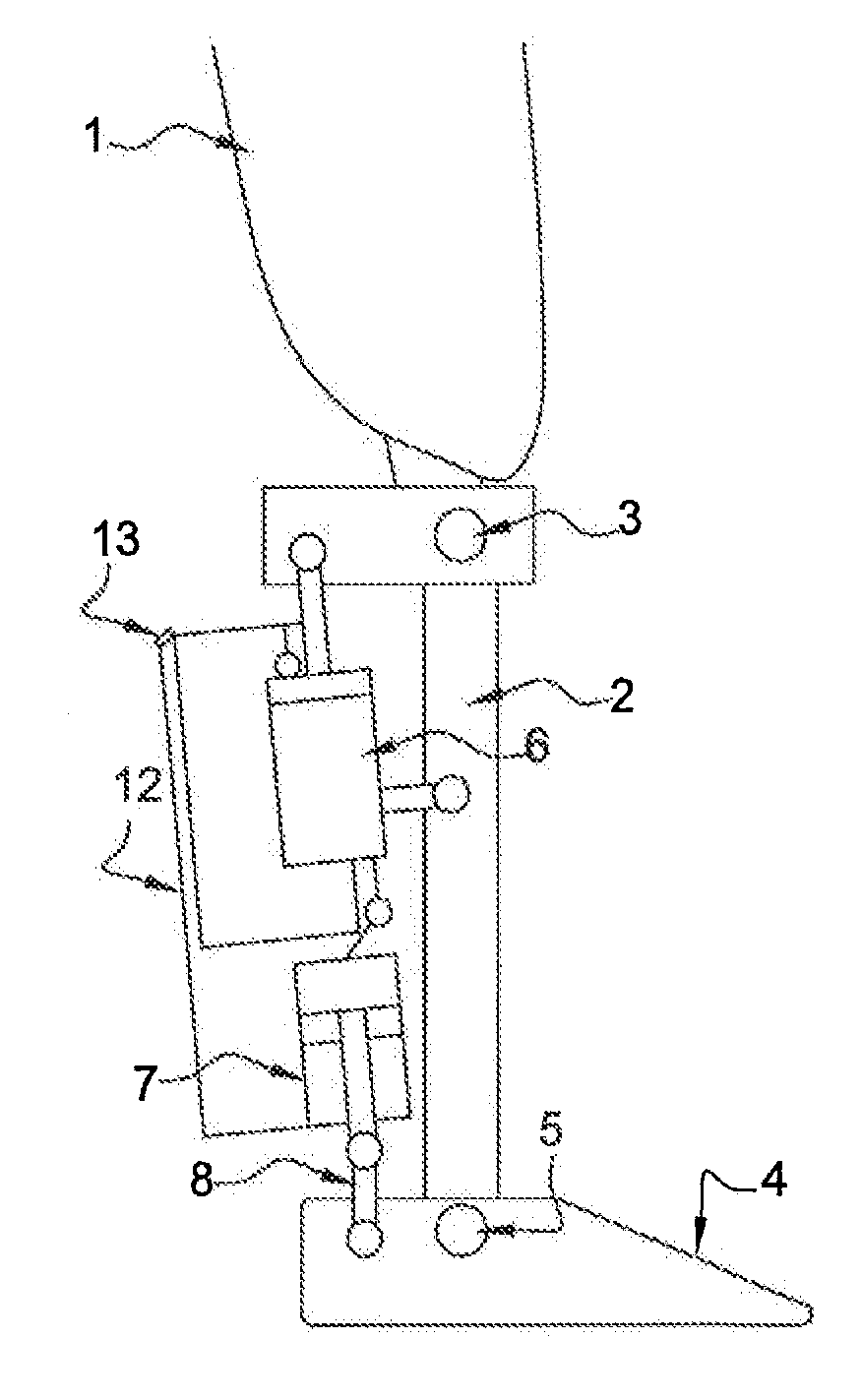
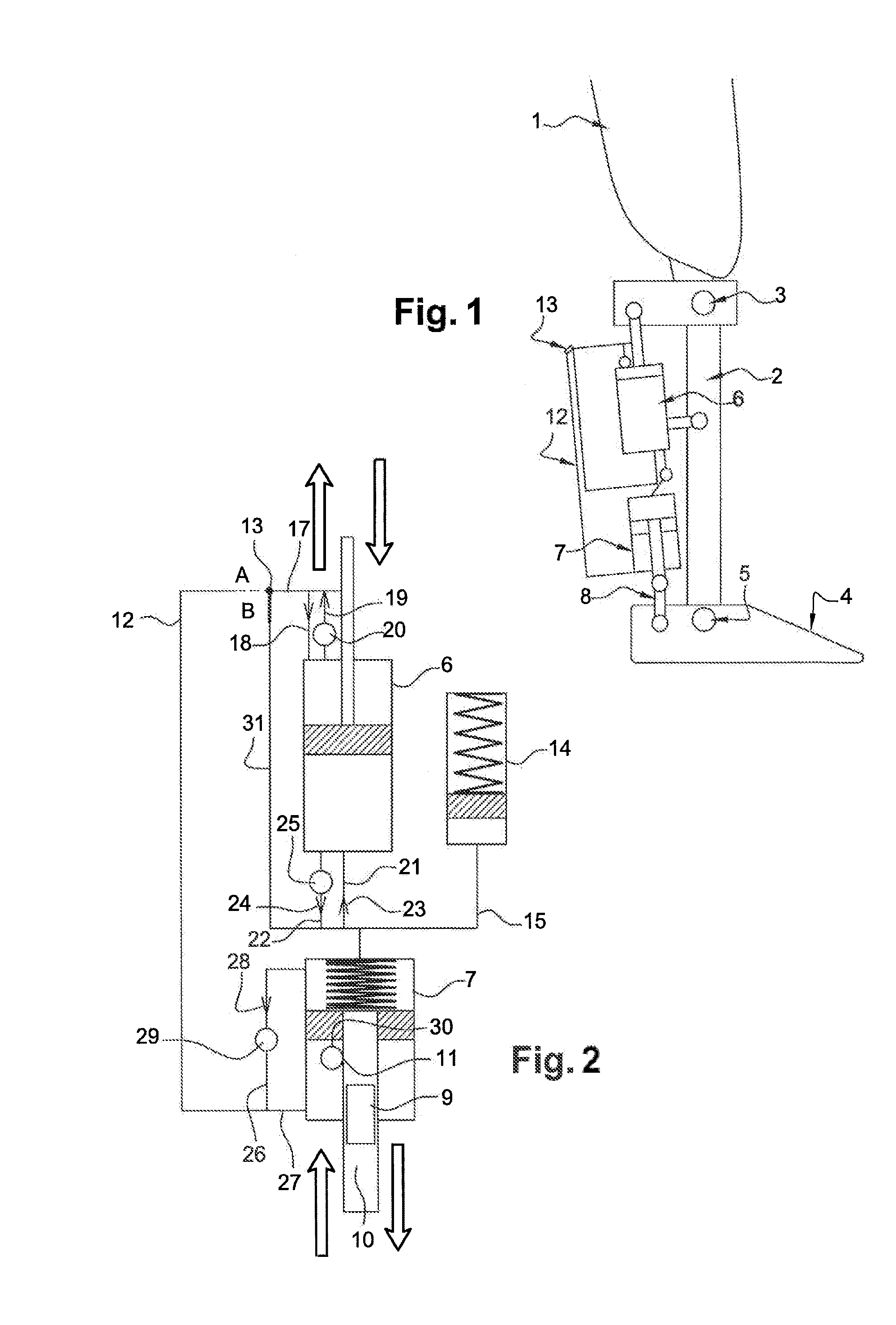
[0053]With reference to FIG. 1, the femoral knee-ankle prosthesis, in compliance with the invention, includes a femoral segment (1) that is suitable for a femoral connection, and a tibial segment (2) connected to the femoral segment (1) based on articulation (3) reproducing the movements of the knee, the said tibial segment (2) being articulated to a foot (4) based on an articulation (5) reproducing the movements of the ankle. The prosthesis consists of a dual purpose hydraulic damper (6) the ends of which are connected respectively to the femoral segment (1) and the tibial segment (2), and a second dual purpose hydraulic damper (7) the ends of which are connected respectively to the tibial segment (2) and the foot (4) using a connecting rod (8).

[0054]With reference to F...


PUM


Abstract

The present invention pertains to a femoral knee-ankle prosthesis intended for persons who are lower-limb amputees but still have a segment suitable for a femoral connection and a tibial connection connected to the femoral segment based on an articulation which reproduces the movements of the knee, the said tibial segment being articulated on one foot based on an articulation reproducing the movements of the ankle, an initial damper the ends of which are joined respectively with the femoral and tibial segments, and another hydraulic damper of which the ends are joined respectively with the tibial and foot segment; the said prosthesis is remarkable in that the chamber of the first hydraulic damper is connected to the chamber of the second hydraulic damper and in that it consists of the means of controlling the first and / or second hydraulic damper depending on the phase of the walking cycle such as the stance phase or the swing phase and / or real-life situations such as stairs, slopes or standing, etc., in such a manner that the flexion of the knee allows the dorsiflexion of the ankle in proportion to the movement of the knee during the stance phase and such that the flexion of the knee results in the dorsiflexion of the ankle during the swing phase.

Description

BACKGROUND[0001]1. Technical Field[0002]The present invention pertains to a knee-ankle prosthesis for lower-limb amputees and in particular to a hydraulic system for the articulation of the knee and ankle controlled by a microprocessor.[0003]2. Description of the Related Art[0004]It is common knowledge that prostheses for femoral amputees generally consist of a prosthetic knee and a foot-ankle assembly. There are multiple types of prosthetic knees; however, there are two broad distinct categories: passive knees and active knees.[0005]Passive mechatronic knees are controlled by microprocessors, and are referred to as passive since they do not provide energy but rather use the energy derived from walking. They contain a hydraulic or magnetorheological damper that controls the flexion and extension movements of the knee, through the use of one or several solenoid valves, of which the flow is managed by a microprocessor. The braking action of the damper is strong in the stance phase in ...

Claims


Application Information

Patent Timeline
Patent Type & Authority Applications(United States)
IPC IPC(8): A61F2/64A61F2/68A61F2/66
CPCA61F2/64A61F2/6607A61F2/68A61F2002/704A61F2002/764A61F2002/748A61F2002/7625A61F2002/7635A61F2002/745A61F2/66A61F2/70A61F2/74A61F2/748
Inventor BONNET, XAVIERDJIAN, FRANCIS
Owner PROTEOR
Why Eureka
Try Eureka