Stent to assist in arteriovenous fistula formation

a technology of arteriovenous fistula and stent, which is applied in the direction of prosthesis, catheter, blood vessel, etc., can solve the problems of limiting the flow rate, many of the avf created do not mature to a usable avf, and the creation of an arteriovenous fistula, etc., to achieve the effect of reducing the turbulent blood flow

Inactive Publication Date: 2015-07-02
QUANTA COMPUTER INC +1
View PDF4 Cites 5 Cited by
  • Summary
  • Abstract
  • Description
  • Claims
  • Application Information

AI Technical Summary

Benefits of technology

[0018]In general, in one embodiment, a method for inserting a stent for use in creation of an arteriovenous fistula, includes the steps of identifying a candidate artery and a candidate vein, dissecting the candidate vein, inserting a stent into the vein, creating a breach in the candidate artery at a desired angle and location, introducing the stent and vein into the candidate artery, forming the stent into a curvature angle selected to minimize turbulent blood flow in an anastomosis formed by the vein and the artery and fastening a distal portion of the stent to the artery to form an anastomosis.

Problems solved by technology

Unfortunately, there are a number of complications that may occur in the creation of an arteriovenous fistula.
Many of the AVF created do not mature to a usable AVF.
This turbulent flow causes blood vessel stenosis—a narrowing of the vessel which limits the available flow rate.

Method used


Image

  • Stent to assist in arteriovenous fistula formation
  • Stent to assist in arteriovenous fistula formation
  • Stent to assist in arteriovenous fistula formation

Examples


Embodiment Construction

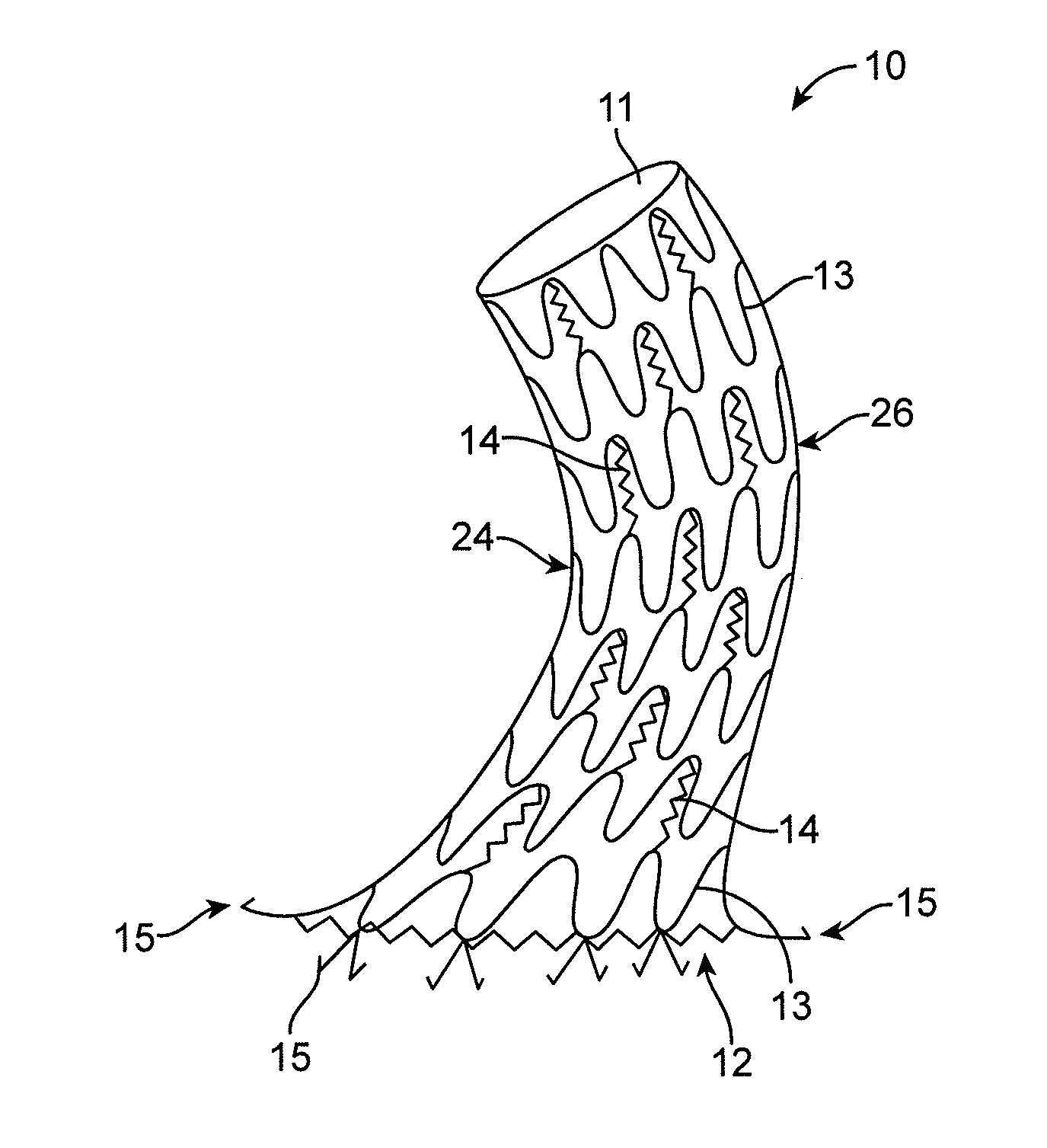
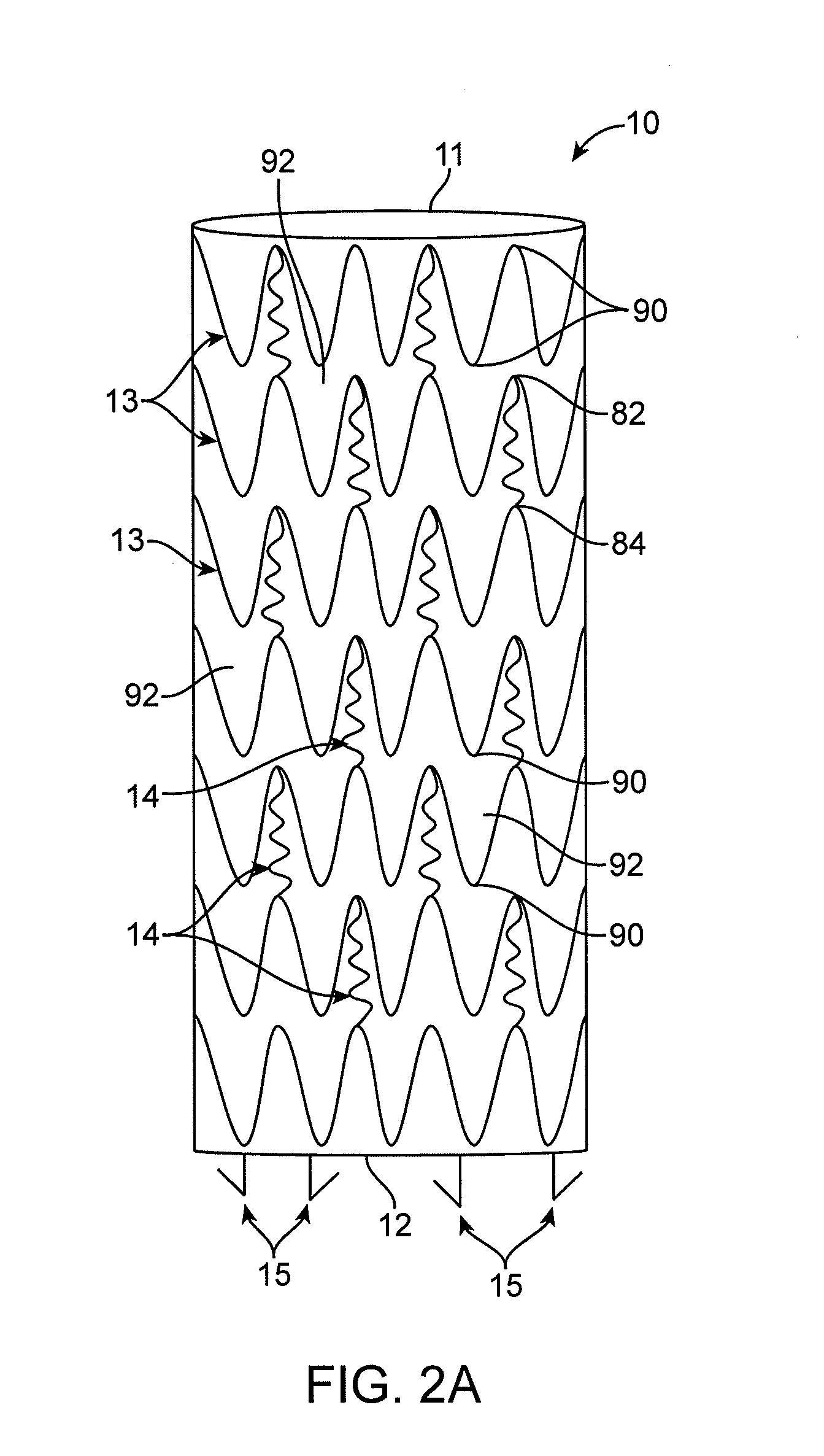
[0038]A stent used in creation of an arteriovenous fistula is now described. While the stent may be used in the creation of a fistula at any location in the body desired by the physician, the ensuing descriptions shall generally refer to a creation of a radiocephalic fistula. A radiocephalic fistula is a fistula created by an anastomosis between the cephalic vein and radial artery of the forearm. As such, any specific reference to a radiocephalic fistula should not be read to limit the scope of the invention.

[0039]Anatomical studies show that all the arteries in the body are branching from the main artery through an obtuse angle to allow a laminar, physiologic blood flow. Also the shape of the arterial bifurcations—a tilted conic trunk—allows for a smooth connection and a laminar blood flow that is beneficial to the arterial function. The shape and “gentle angles” of bifurcations of the arteries in the body are a testimony that this is the most efficient way to ensure a good functio...


PUM

PropertyMeasurementUnit
anastomosis angleaaaaaaaaaa

Abstract

There is described an arteriovenous fistula stent, having a tubular body comprising a series of sinusoidal shaped struts along the length of the tubular body. A plurality of curvilinear connectors extend between and are attached to adjacent struts wherein a first end of a connector is attached to a distal face of a proximal strut apex and a second end of a connector is attached to a proximal face of a distal strut apex. A pair of unconnected strut apexes are between pairs of connected apexes. When the tubular body is in a stowed configuration a proximal aperture and a distal aperture are circular and when the tubular body is in a deployed configuration the distal aperture is oblong or ovoid. There is also described a method for inserting a stent for use in creation of an arteriovenous fistula by identifying a candidate artery and a candidate vein and dissecting the candidate vein. Next, inserting a stent into the vein and creating a breach in the candidate artery at a desired angle and location. Next, introducing the stent and vein into the candidate artery and forming the stent into a curvature angle selected to minimize turbulent blood flow in an anastomosis formed by the vein and the artery. Optionally, there is a step of fastening a distal portion of the stent to the artery.

Description

CROSS REFERENCE TO RELATED APPLICATIONS[0001]This application claims priority to U.S. Provisional Patent Application No. 61 / 661,133, filed Jun. 18, 2012, titled “STENT TO ASSIST IN ARTERIOVENOUS FISTULA FORMATION,” which is herein incorporated by reference in its entirety.INCORPORATION BY REFERENCE[0002]All publications and patent applications mentioned in this specification are herein incorporated by reference to the same extent as if each individual publication or patent application was specifically and individually indicated to be incorporated by reference.FIELD[0003]The present invention relates to stents or other devices used to assist medical personnel in vascular access procedures, particularly those procedures involving the creation of an arteriovenous fistula.BACKGROUND[0004]Nearly 2.5 million patients worldwide suffer from End Stage Renal Disease (ESRD). To treat ESRD, patients are either subjected to a kidney transplant or undergo hemodialysis. Though acting as artificial...

Claims


Application Information

Patent Timeline
Patent Type & Authority Applications(United States)
IPC IPC(8): A61F2/86A61B17/11A61M25/10
CPCA61F2/86A61M25/104A61B2017/1107A61F2220/0008A61B17/11A61F2/07A61F2/915A61F2/958A61F2002/821A61F2002/91558A61F2230/0013A61L31/06A61L31/14A61F2220/0016A61F2230/0054C08L67/04A61B2017/1135A61F2/06A61F2/064A61M1/3655
Inventor FLORESCU, MARIUS C.
Owner QUANTA COMPUTER INC
Why Eureka
Try Eureka