Apparatus and Method for use of Rotating Arc Process Welding

a technology of rotating arc and apparatus, applied in the field of arc welding, can solve the problems of often encountered setup problems

Inactive Publication Date: 2015-07-09
WELD REVOLUTION
View PDF12 Cites 10 Cited by
  • Summary
  • Abstract
  • Description
  • Claims
  • Application Information

AI Technical Summary

Problems solved by technology

Set-up problems are often encountered during welding.

Method used


Image

  • Apparatus and Method for use of Rotating Arc Process Welding
  • Apparatus and Method for use of Rotating Arc Process Welding
  • Apparatus and Method for use of Rotating Arc Process Welding

Examples


Embodiment Construction

[0029]The present invention extends the state of the art beyond that disclosed in my previous patents. Improvements involve control of variables in the weld process, particularly continuous adjustments made in response to continuous monitoring of the weld and the impact such adjustments cause.

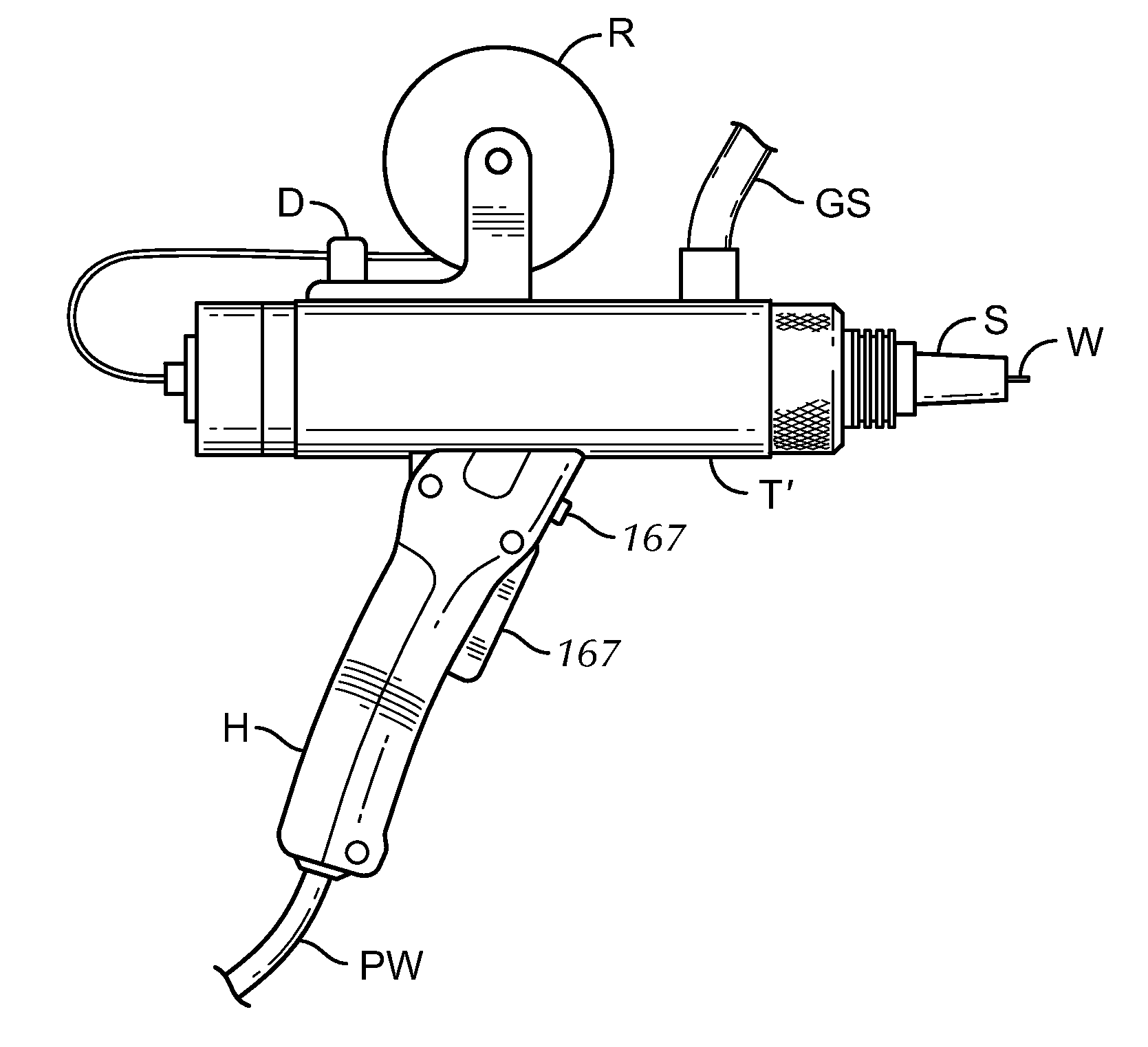
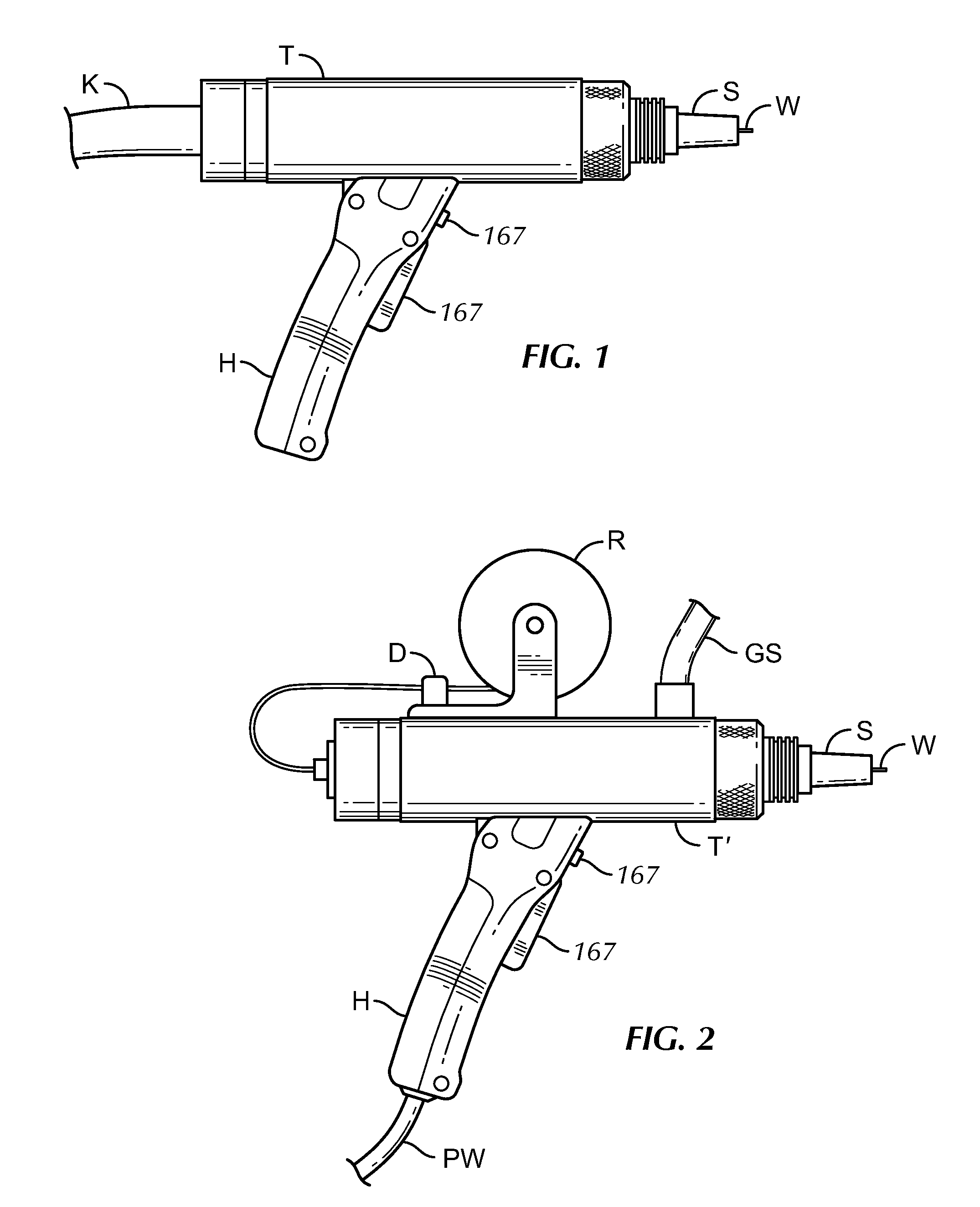
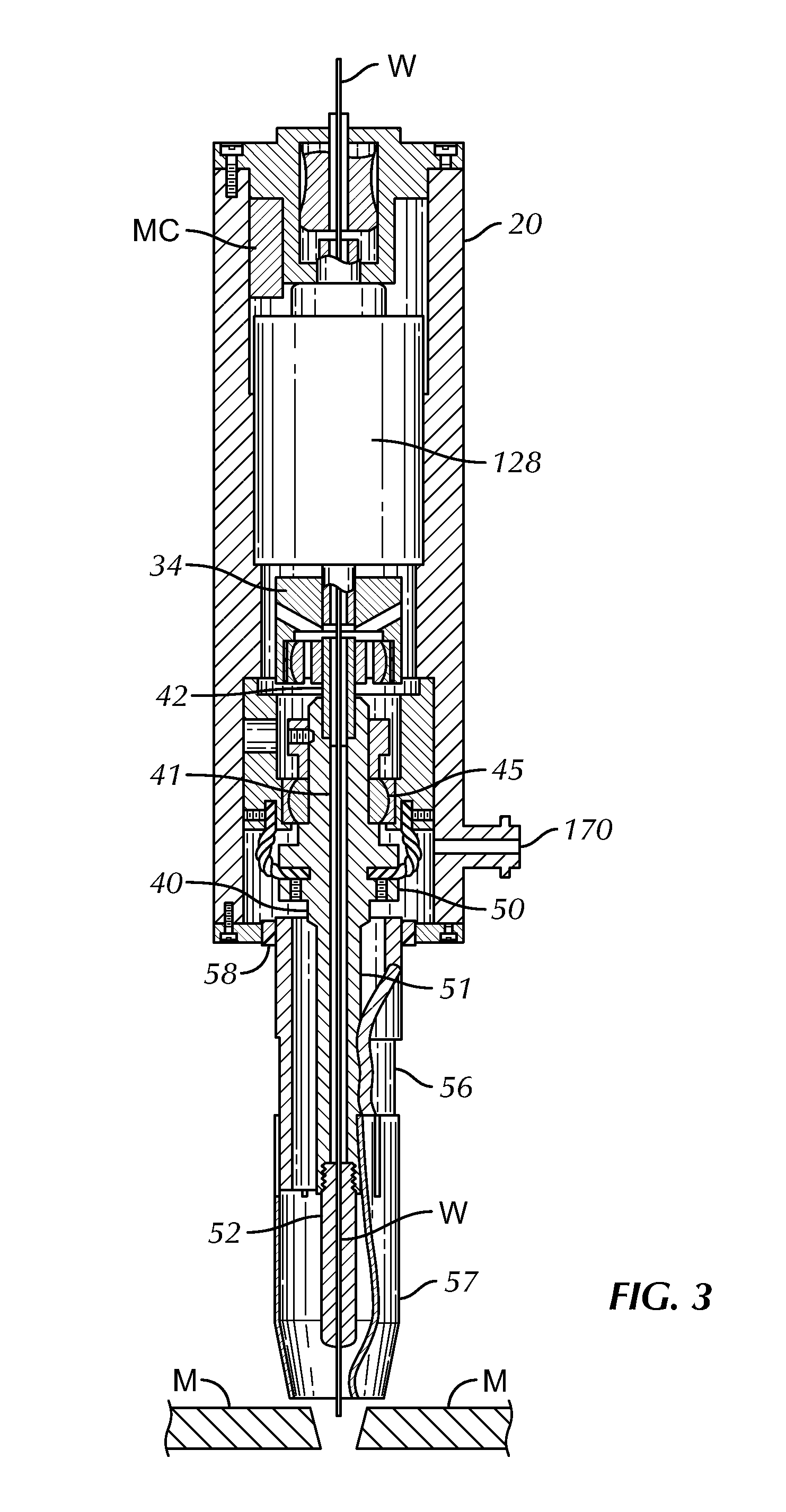
[0030]In prior designs, a variable speed electrical motor was coupled with a variable speed control which varied the speed of the motor by varying the voltage until the approximate frequency of rotation was obtained. Improvements discussed herein comprise utilization of stepping motors (128) with accompanying electronic control (MC) for precise positioning of the motor's shaft, rotation speed, and direction. Additional improvements comprise adjusting the length of the torch's elongated wand and tip to further adjust the physical characteristics of the electrode's path.

[0031]The improvements further comprise separation of gas, electrode, and power into separate feeds for more precise routing, co...


PUM

PropertyMeasurementUnit
diametersaaaaaaaaaa
feedback resistanceaaaaaaaaaa
lengthsaaaaaaaaaa

Abstract

An arc welding apparatus that imparts a rotational movement to the tip of the consumable electrode to cause molten metal to be thrown by centrifugal force against the sidewall of the slot between metal work pieces being welded. The welding apparatus being configurable to control speed, direction, and / or placement of the electrical arc in relation to the slot. The welding apparatus being configurable to pair with other similar devices and to be cooperatively operated in close proximity and\or on a single weld puddle to accomplish larger and / or complex welds in rapid, repeatable succession.

Description

CROSS-REFERENCE TO RELATED APPLICATIONS[0001]This application claims priority to PCT Application #PCT / US13 / 49700 titled “Apparatus and Method for Use of Rotating Arc Process Welding” filed in the US receiving office on 9 Jul. 2013, which is incorporated herein by reference.STATEMENT REGARDING FEDERALLY SPONSORED RESEARCH OR DEVELOPMENT[0002]Not applicable.NAMES OF PARTIES TO A JOINT RESEARCH AGREEMENT[0003]Not applicable.REFERENCE TO SEQUENCE LISTING, A TABLE, OR A COMPUTER PROGRAM LISTING APPENDIX SUBMITTED ON COMPACT DISC[0004]Not applicable.BACKGROUND OF THE INVENTION[0005]The present invention relates to arc welding which uses a continuous feed of a consumable wire electrode and more particularly to such continuous arc welding where lateral movement is imparted to the arcing end of the electrode in a controlled and continually adjustable manner.[0006]Continuous arc welding is affected by variables such as the use of selected gases and blends of gases; selected fluxes; metals or ...

Claims


Application Information

Patent Timeline
Patent Type & Authority Applications(United States)
IPC IPC(8): B23K9/133
CPCB23K9/133B23K9/29B23K9/0216B23K9/287B23K9/16B23K9/28B23K9/30
Inventor ROEN, RICHARD ACHRISTOFFERSON, ERIC M.WALL, JR., MICHAEL S.
Owner WELD REVOLUTION
Why Eureka
Try Eureka