Lever mechanism to facilitate edge coupling of circuit board

a technology of edge coupling and latch mechanism, which is applied in the direction of electrical apparatus construction details, electrical apparatus casings/cabinets/drawers, instruments, etc., can solve problems such as bend or crack, damage to the connectors or the circuit boards themselves

Active Publication Date: 2015-07-09
ADVANCED MICRO DEVICES INC
View PDF3 Cites 18 Cited by
  • Summary
  • Abstract
  • Description
  • Claims
  • Application Information

AI Technical Summary

Problems solved by technology

The conventional approach involves a technician pushing the circuit board from an edge furthest away from the connecting backplane, forcing the circuit board toward the server backplane and introducing unstable compression forces along the length of the circuit board, which can cause it to bend or crack.
Further, in many implementations, the technician building, maintaining, or modifying the computing system does not have a clear view of the slot connector on the backplane or motherboard during the circuit board coupling process, and thus is required to attempt to couple a connector on the circuit board with the corresponding connector without visual cues.
This frequently leads to misalignment resulting in damage to the connectors or the circuit boards themselves.

Method used


Image

  • Lever mechanism to facilitate edge coupling of circuit board
  • Lever mechanism to facilitate edge coupling of circuit board
  • Lever mechanism to facilitate edge coupling of circuit board

Examples


Embodiment Construction

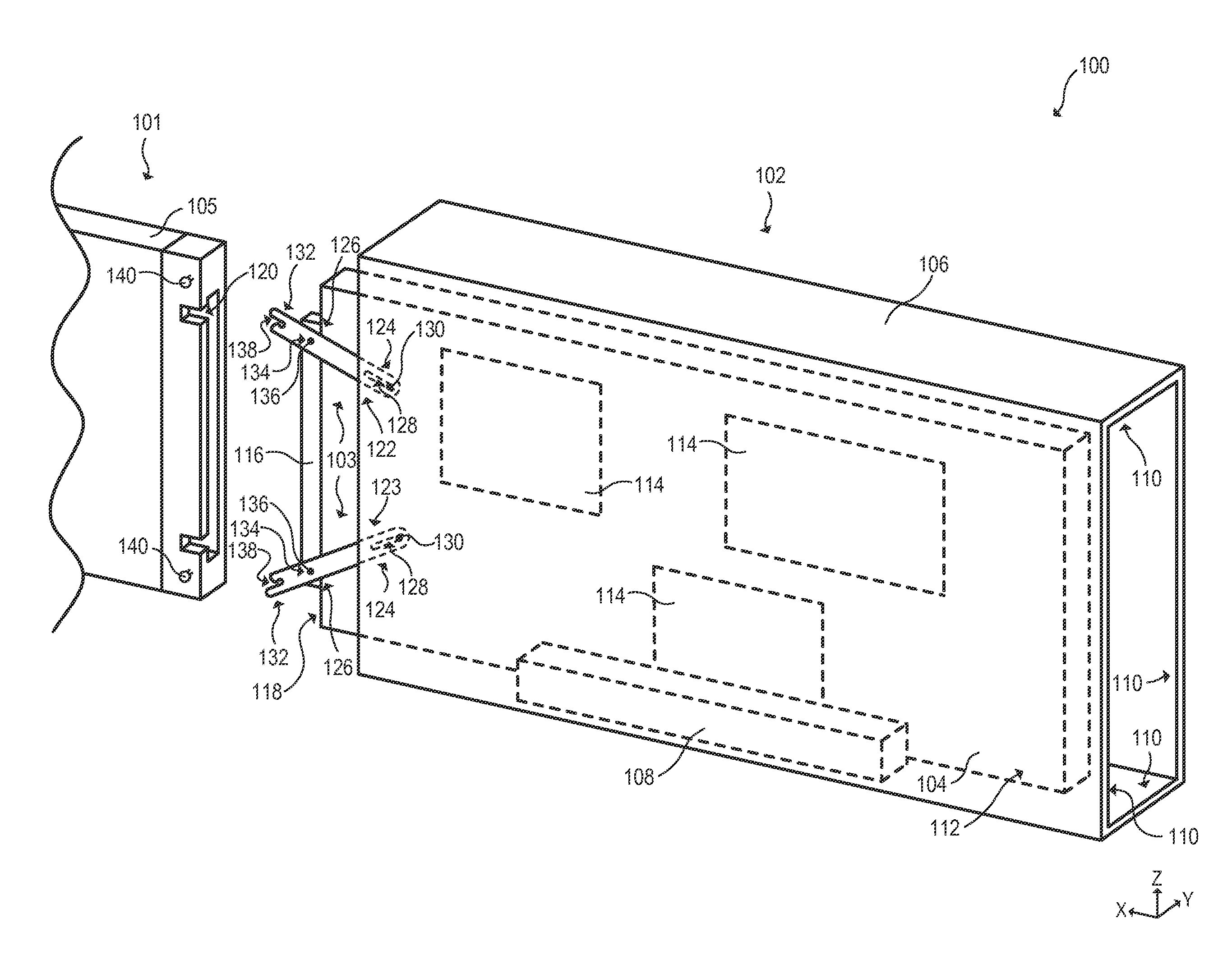
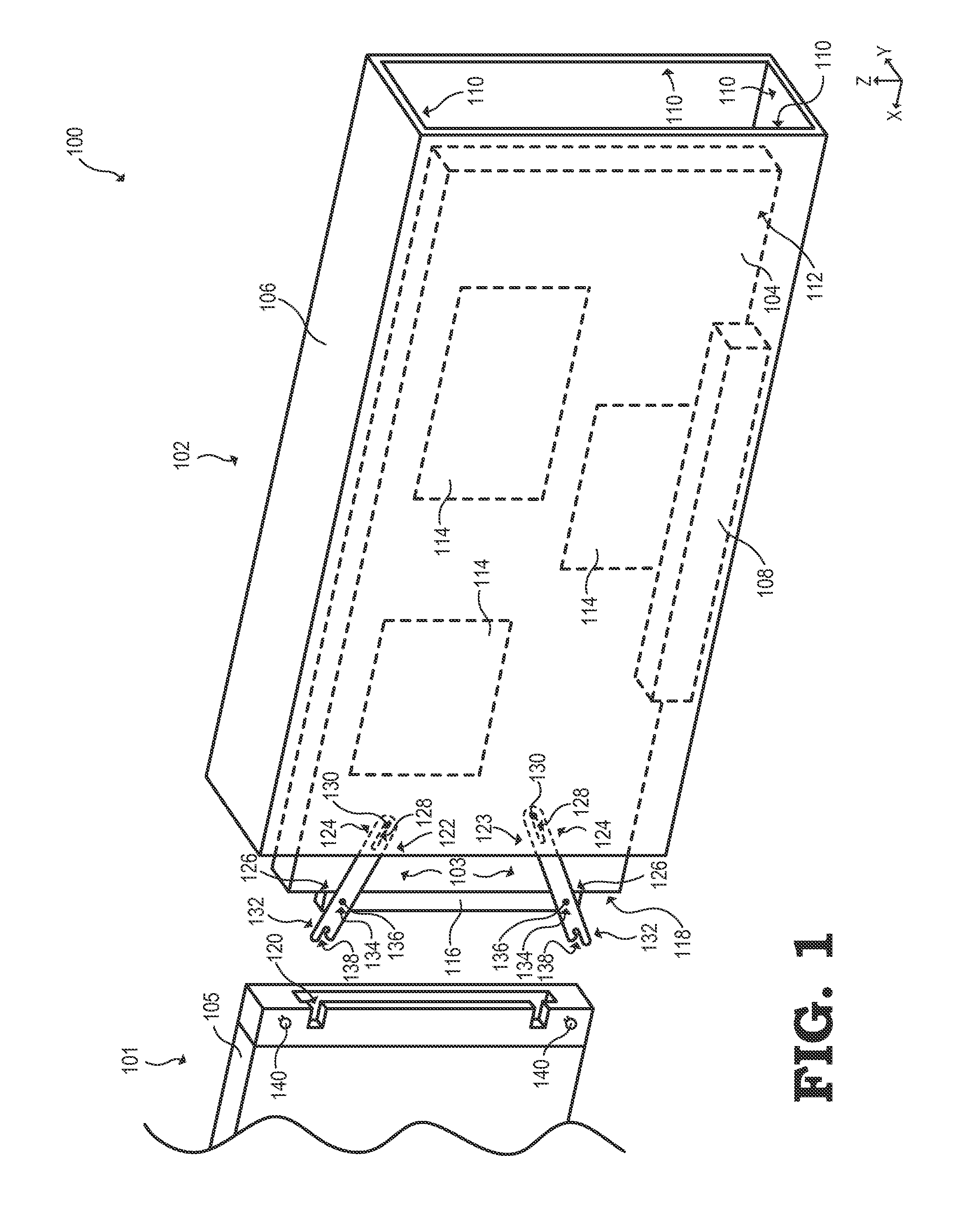
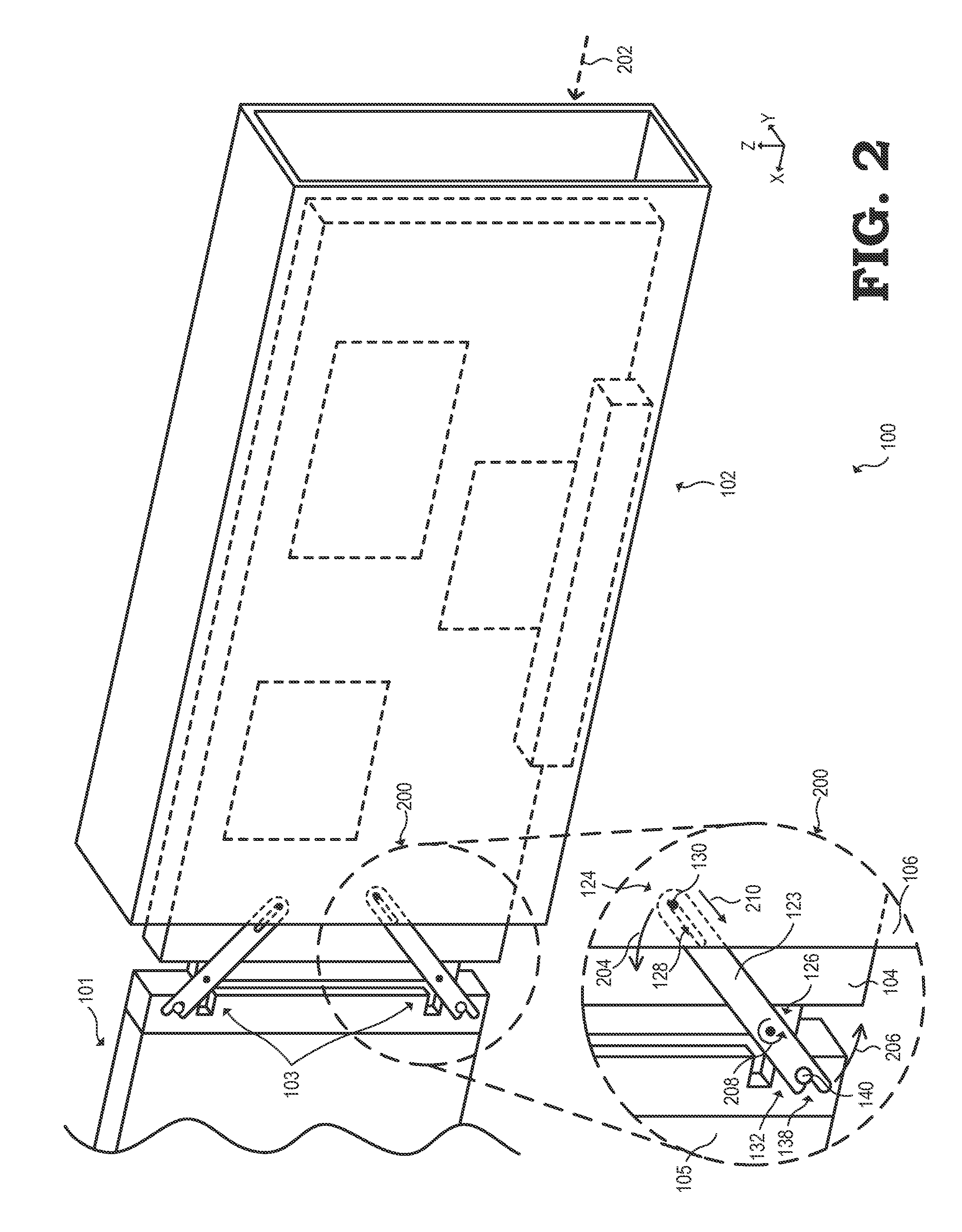
[0014]FIGS. 1-8 illustrate example embodiments of a lever mechanism that facilitates coupling of a connector of a sliding board with a corresponding connector. For example, the lever mechanism could be used to facilitate coupling of a server blade, printed circuit board (PCB), or other sliding board with a server backplane, motherboard, PCB, other circuit board, or a floating connector terminating a cable. In the illustrated embodiments, the sliding board having the connector is at least partially enclosed by an enclosure that allows the sliding board to slide within the enclosure toward and away from a connection surface of the corresponding connector. The lever mechanism is illustrated as a pair of pivot levers, each connected at a proximal end to an interior surface of the enclosure and at a pivot point to the sliding board. The distal end of each pivot lever has an opening to receive and facilitate maintaining a fastening component attached to the corresponding connector.

[0015]W...


PUM


Abstract

A lever mechanism facilitates coupling of a sliding board and a connector. A sliding board is partially enclosed by a sliding board enclosure, such that the sliding board is slidable relative to the enclosure. A pair of pivot levers is disposed between the sliding board and the enclosure. Each pivot lever is connected at a proximal end to the enclosure and at a pivot point to the sliding board. A distal end of the pivot lever is removably engageable with a second circuit board. The lever mechanism translates a pushing force on the enclosure to a pulling force on the sliding board, aligning and eventually coupling the sliding board with the connector.

Description

BACKGROUND[0001]1. Field of the Disclosure[0002]The present disclosure relates generally to modular computing systems employing edge-coupled circuit boards and, more particularly, to the coupling of a circuit board to a backplane, motherboard, or other circuit board.[0003]2. Description of the Related Art[0004]Modular computing systems often rely on the connection of one or more circuit boards to a corresponding backplane, motherboard, or other circuit board. To illustrate, server systems often employ a server chassis having a backplane with slot connectors into which one or more server blades are inserted or connected, and desktop computers often employ expansion slots into which expansion cards may be inserted and connected. The conventional approach involves a technician pushing the circuit board from an edge furthest away from the connecting backplane, forcing the circuit board toward the server backplane and introducing unstable compression forces along the length of the circui...

Claims


Application Information

Patent Timeline
Patent Type & Authority Applications(United States)
IPC IPC(8): H05K7/14G06F1/18
CPCH05K7/1409G06F1/186H05K7/1487H05K7/1461
Inventor FRICKER, JEAN-PHILIPPE
Owner ADVANCED MICRO DEVICES INC
Why Eureka
Try Eureka