System for automatically tracking a target

a technology of automatic tracking and target, applied in the field of automatic tracking systems, can solve the problems of only providing a limited and static field of view for dash-mounted recorders, and still being difficult for consumers and professionals to acquire quality and perspectiv

a technology of automatic tracking and target, applied in the field of automatic tracking systems, can solve the problems of only providing a limited and static field of view for dash-mounted recorders, and still being difficult for consumers and professionals to acquire quality and perspectiv

US20150206012A1Inactive Publication Date: 2015-07-23JIGABOT

Image

  • System for automatically tracking a target
  • System for automatically tracking a target
  • System for automatically tracking a target

Examples


Embodiment Construction

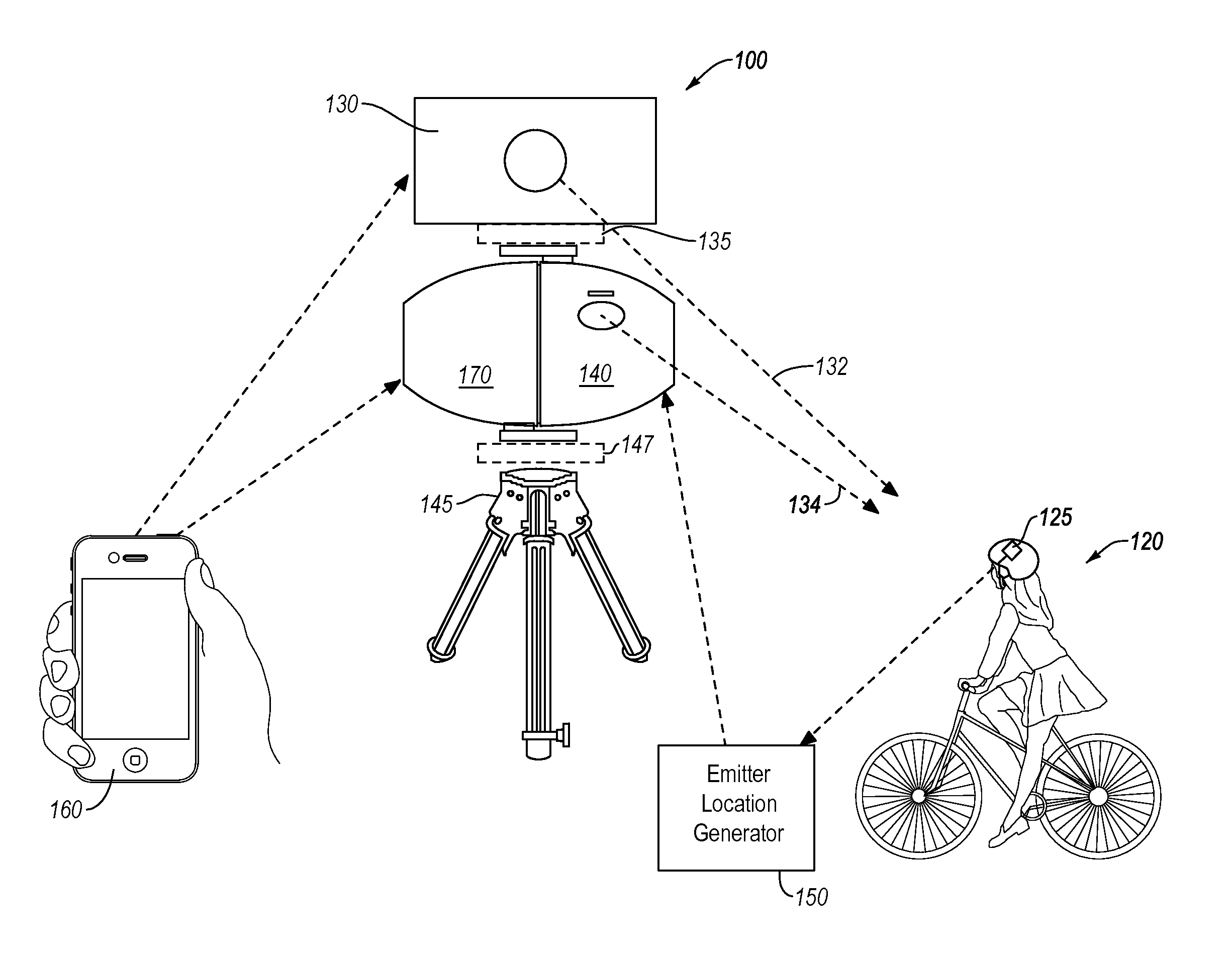
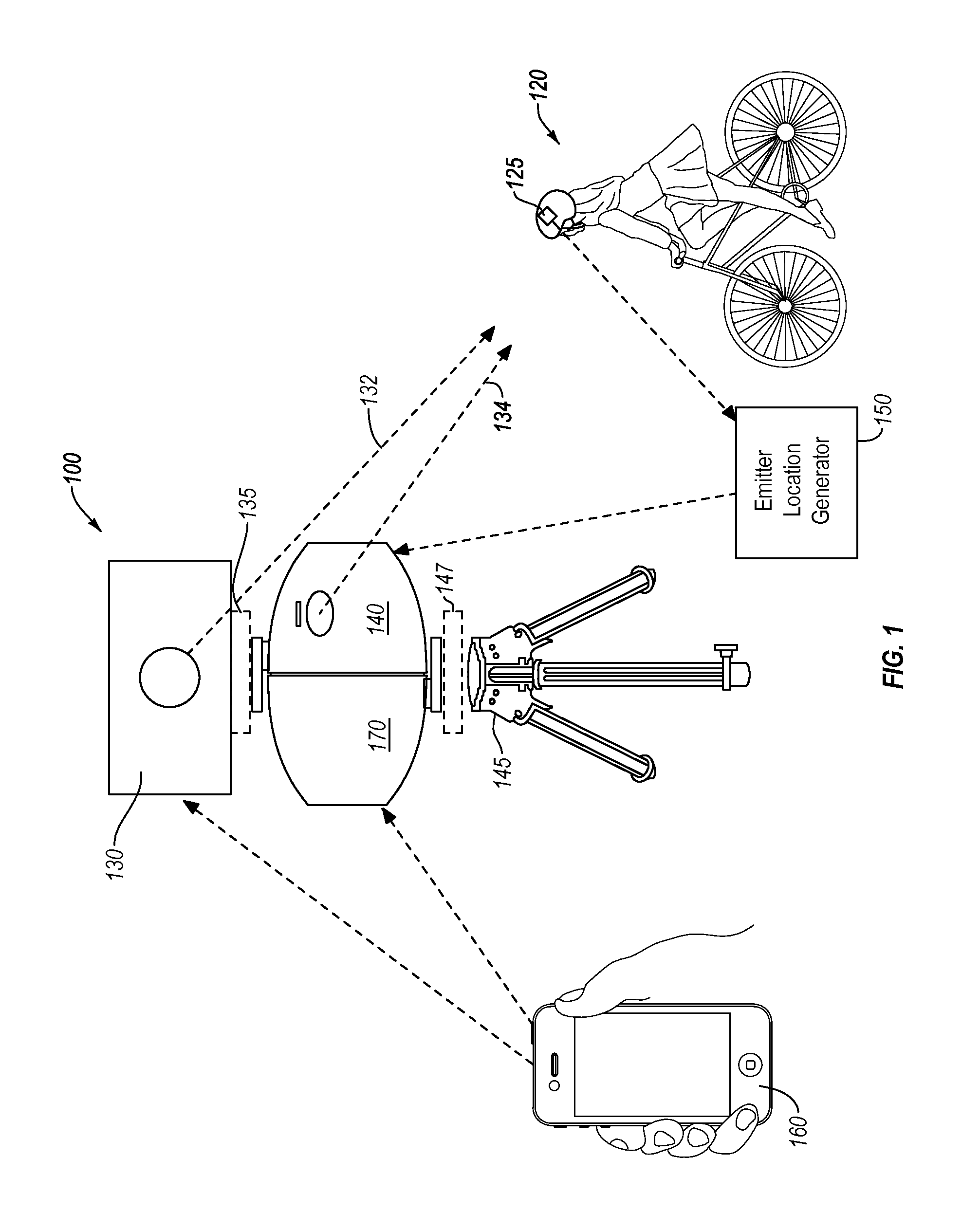
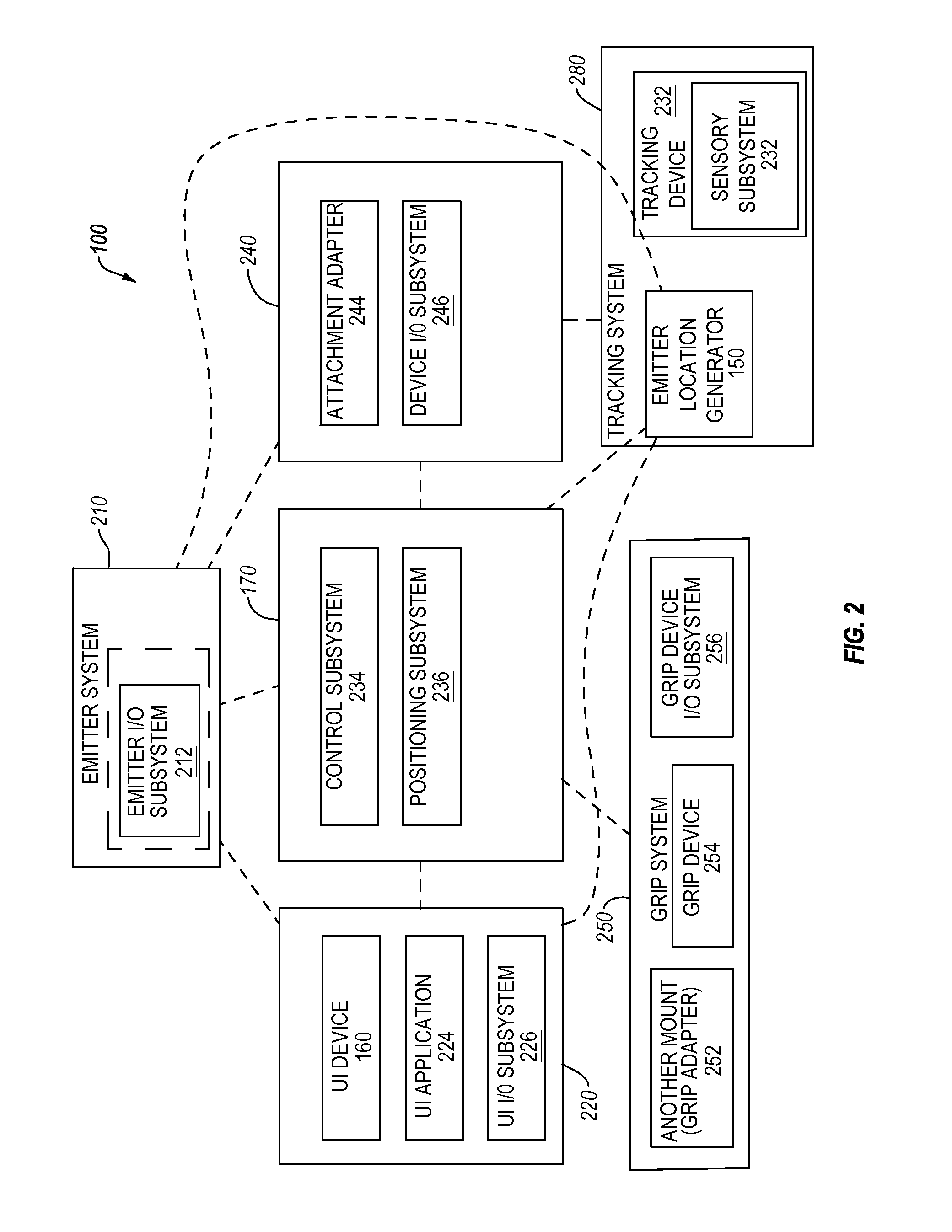
[0019]The present invention extends to systems, methods, and apparatus configured to automatically track one or more specific targets. In particular, implementations of the present invention can utilize one or more external tracking devices to track the movements of the one or more specific targets. Additionally, in at least one implementation, the tracking system can also include one or more cameras that can provide tracking data to the tracking system.

[0020]Accordingly, one or more implementations of a system for automatically tracking a target include using an external and independent tracking device, referred to herein as a emitter location generator (“ELG”), to track the target and then forward the tracking information to a physically separate control module. As used herein, an ELG refers primarily to a tracking device that is not physically integrated into the same unit as the control device and / or the audiovisual device. When describing the various features of the ELG and / or ...


PUM


Abstract

A method for tracking a cinematography target that has been associated with an emitter can comprise receiving an indication to track a particular identifier. The particular identifier can be associated with an object of interest. The method can further comprise identifying, using at least one tracker component, a direction associated with the particular identifier. The method can also include calculating a motor actuation sequence necessary to actuate a control component to track the object of interest with an audiovisual device. The method can further comprise actuating at least one motor to track the object of interest.

Description

CROSS-REFERENCE TO RELATED APPLICATIONS[0001]This application claims priority to U.S. Provisional Patent Application Ser. No. 61 / 965,048 filed on Jan. 18, 2014, entitled “INTEGRATING NATIVE VIDEO WITHIN A TRACKING SYSTEM,” and to U.S. Provisional Patent Application Ser. No. 61 / 965,444 filed on Jan. 30, 2014, entitled “GRID & ANGULAR DATA TRACKING WITHIN A TRACKING SYSTEM,” and to U.S. Provisional Patent Application Ser. No. 61 / 965,967 filed on Feb. 10, 2014, entitled “3D VISION AND FACIAL TRACKING.” All the aforementioned applications are incorporated by reference herein in their entirety.BACKGROUND OF THE INVENTION[0002]1. Technical Field[0003]The present invention relates generally to automated tracking systems.[0004]2. Background and Relevant Art[0005]Recently, with the market arrival of low cost, high quality digital recorders, many non-professional and professional consumers have increasingly used recorders to document a variety of different events. For example, many consumers ...

Claims


Application Information

Patent Timeline
23 Jul 2015
Publication
US20150206012A1
IPC
G06K9/00
CPC
G06K2009/00738; G06K9/00711; G06V20/44; G06V20/40
Inventors
STOUT, RICHARD F.; JOHNSON, KYLE K.