Switchable antenna array

a technology of switching antennas and arrays, applied in the direction of antennas, electronic switching, pulse techniques, etc., can solve the problems of power loss and noise, noise and interference,

a technology of switching antennas and arrays, applied in the direction of antennas, electronic switching, pulse techniques, etc., can solve the problems of power loss and noise, noise and interference,

US20150207536A1Active Publication Date: 2015-07-23QUALCOMM INC

Image

  • Switchable antenna array
  • Switchable antenna array
  • Switchable antenna array

Examples


Embodiment Construction

[0010]The detailed description set forth below is intended as a description of exemplary designs of the present disclosure and is not intended to represent the only designs in which the present disclosure can be practiced. The term “exemplary” is used herein to mean “serving as an example, instance, or illustration.” Any design described herein as “exemplary” is not necessarily to be construed as preferred or advantageous over other designs. The detailed description includes specific details for the purpose of providing a thorough understanding of the exemplary designs of the present disclosure. It will be apparent to those skilled in the art that the exemplary designs described herein may be practiced without these specific details. In some instances, well-known structures and devices are shown in block diagram form in order to avoid obscuring the novelty of the exemplary designs presented herein.

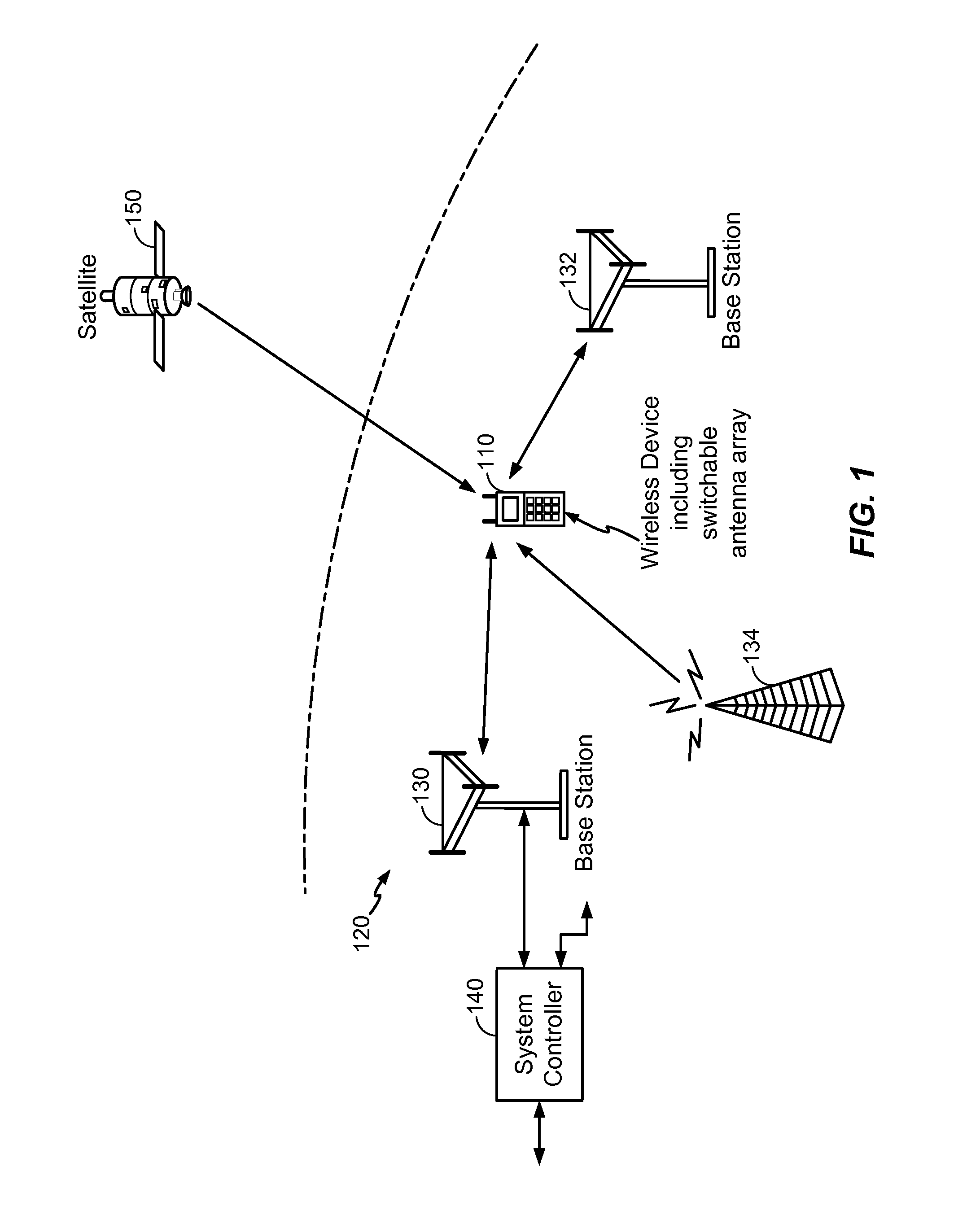
[0011]FIG. 1 shows a wireless device 110 communicating with a wireless communication s...


PUM


Abstract

An apparatus includes an impedance circuit and a plurality of inductors coupled to the impedance circuit. Each of the plurality of inductors is coupled in parallel to a corresponding switch of a plurality of switches.

Description

I. CROSS-REFERENCE TO RELATED APPLICATIONS[0001]The present application claims priority from U.S. Provisional Patent Application No. 61 / 928,660, filed Jan. 17, 2014 and entitled “SWITCHABLE ANTENNA ARRAY,” the content of which is incorporated by reference in its entirety.II. FIELD[0002]The present disclosure is generally related to a switchable antenna array.III. DESCRIPTION OF RELATED ART[0003]Advances in technology have resulted in smaller and more powerful computing devices. For example, there currently exist a variety of portable personal computing devices, including wireless computing devices, such as portable wireless telephones, personal digital assistants (PDAs), and paging devices that are small, lightweight, and easily carried by users. More specifically, portable wireless telephones, such as cellular telephones and Internet protocol (IP) telephones, can communicate voice and data packets over wireless networks. Further, many such wireless telephones include other types of...

Claims


Application Information

Patent Timeline
23 Jul 2015
Publication
US20150207536A1
IPC
H04B1/44; H03H11/02
CPC
H03H11/02; H04B1/44; H01Q3/24; H03H7/465; H04B1/0064; H03K2017/066
Inventors
YEHEZKELY, ALON; LEVINGER, TAMIR