Fabric rolling apparatus for circular knitting machines

Active Publication Date: 2015-07-30
PAI LUNG MACHINERY MILL CO LTD
View PDF6 Cites 4 Cited by
  • Summary
  • Abstract
  • Description
  • Claims
  • Application Information

AI Technical Summary

Benefits of technology

[0005]The primary object of the present invention is to solve the inconsistent quality fabric problem of the initial rolli

Problems solved by technology

As a result, a portion of the fabric in the entire roll of fabric does not meet require

Method used


Image

  • Fabric rolling apparatus for circular knitting machines
  • Fabric rolling apparatus for circular knitting machines
  • Fabric rolling apparatus for circular knitting machines

Examples


Example

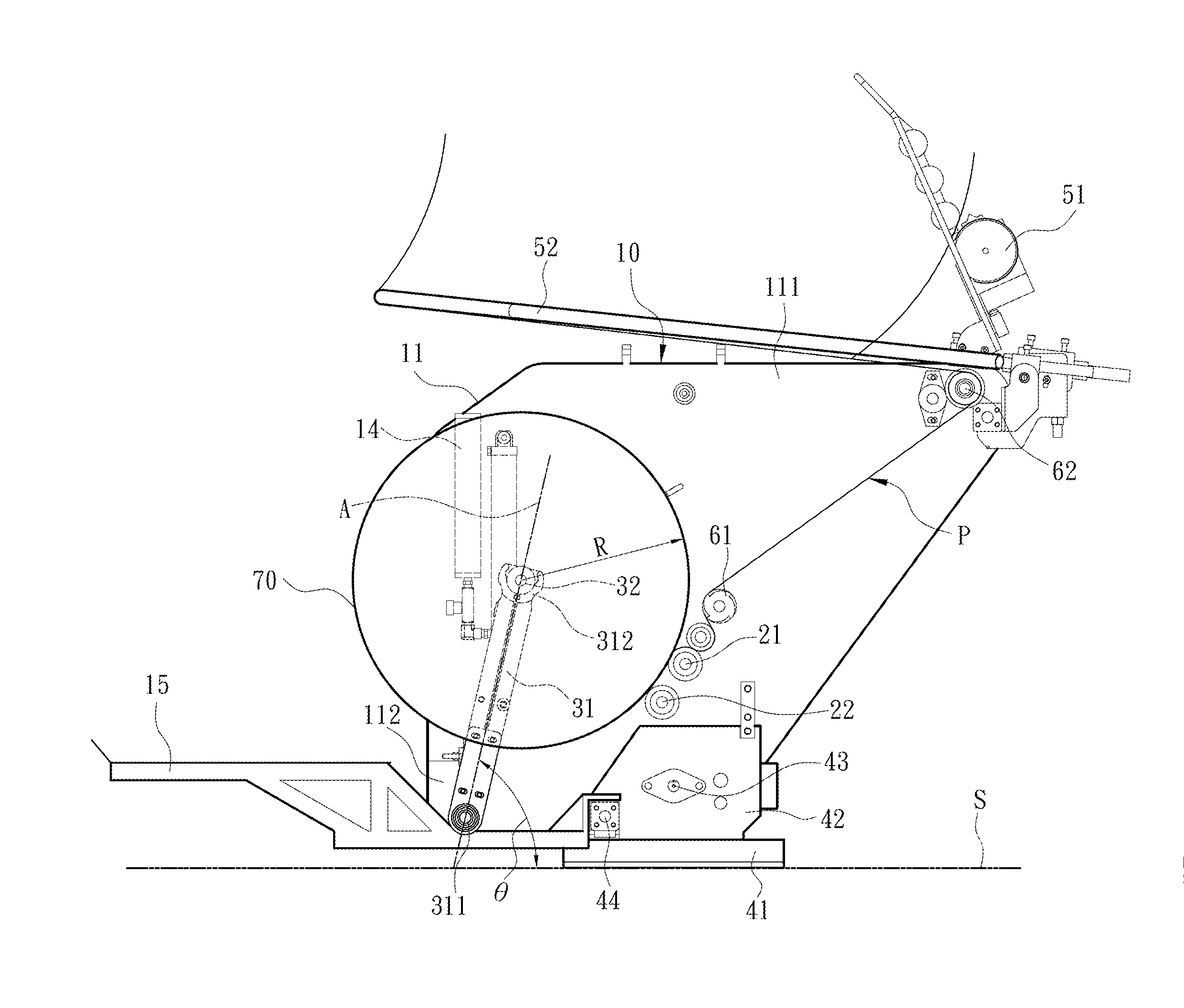
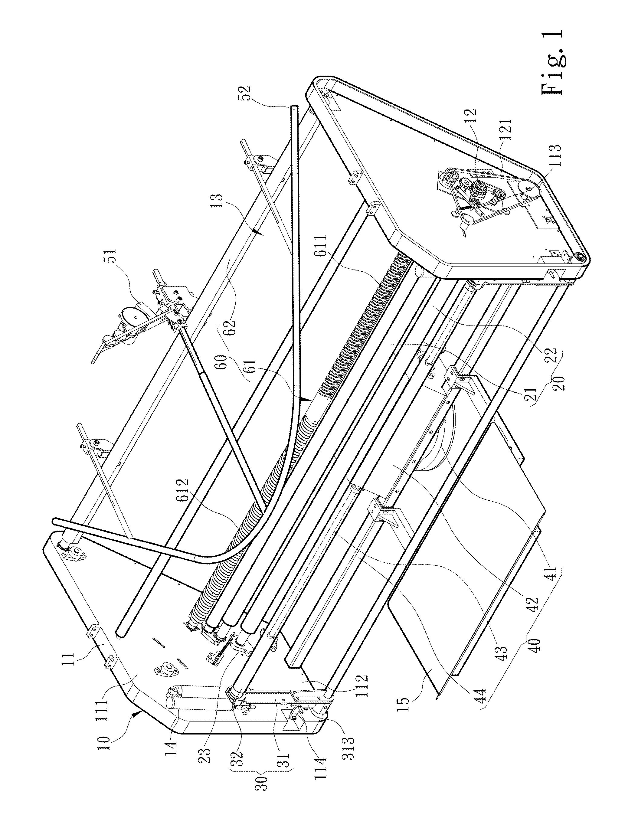
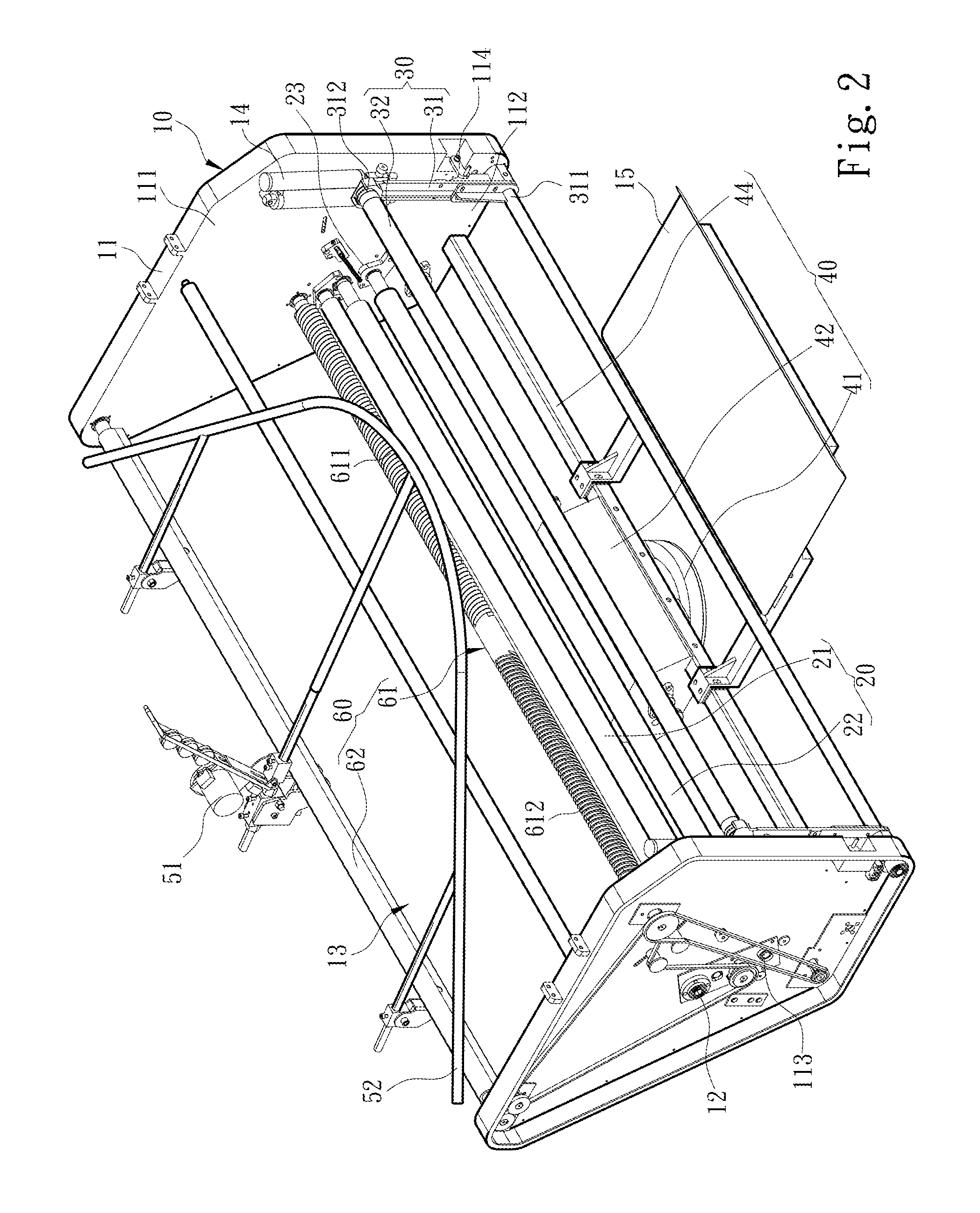
[0029]Please referring to FIGS. 1, 2 and 3A, the present invention aims to provide a fabric rolling apparatus that is located beneath a circular knitting machine (not shown in the drawings). It is driven by the circular knitting machine to revolve and receive a fabric 70 knitted by the circular knitting machine. The fabric rolling apparatus comprises a bracket 10, a transmission rod set 20 located on the bracket 10 and a revolving fabric collection mechanism 30. The bracket 10 includes two side boxes 11 corresponding to each other, a drive mechanism 12 located in the side boxes 11 and a fabric rolling space 13 located between the two side boxes 11. Each side box 11 has a top side 111 close to the circular knitting machine and a bottom side 112 remote from the circular knitting machine. The transmission rod set 20 is located in the fabric rolling space 13 and driven by the drive mechanism 12 to rotate and guide the fabric 70 to move along a fabric transporting path P. To provide driv...


PUM


Abstract

A fabric rolling apparatus is driven by a circular knitting machine to revolve and receive a knitted fabric. The fabric rolling apparatus comprises a bracket, a transmission rod set located on the bracket and a revolving fabric collection mechanism. The bracket includes two side boxes corresponding to each other and a drive mechanism located in each side box. Each side box has a top side and a bottom side. The drive mechanism drives the transmission rod set to guide movement of the fabric. The revolving fabric collection mechanism includes two revolving arms hinged respectively on the side boxes and a fabric rolling rod driven by the transmission rod set to revolve and roll the fabric. Each revolving arm has a revolving end hinged on the bottom side of the side box and a holding end connected to the fabric rolling rod at an elevation higher than the revolving end.

Description

FIELD OF THE INVENTION[0001]The present invention relates to a fabric rolling apparatus for circular knitting machines and particularly to a fabric rolling apparatus for circular knitting machines that can adjust fabric pressing force.BACKGROUND OF THE INVENTION[0002]Circular knitting machines are fundamental equipments in the textile industry. They usually include a plurality of knitting needles on a needle dial and a cylinder to knit yarns of same or different materials to circular fabrics. The knitted fabrics are rolled into a bundle of flat cloth through a fabric rolling machine located below each circular knitting machine.[0003]A conventional fabric rolling machine, such as U.S. Pat. No. 7,441,723, includes a frame, a transmission shaft hinged on the side walls of the frame, a displacement track defined by a lump and a stopper that are parallel with each other and a fabric rolling rod located in the displacement track and driven by the transmission shaft. When the fabric rollin...

Claims


Application Information

Patent Timeline
IPC IPC(8): D04B15/88
CPCD04B15/88
Inventor CHEN, SHIH-CHILEE, PENG CHENG
Owner PAI LUNG MACHINERY MILL CO LTD
Why Eureka
Try Eureka