Laser radar ranging system

A ranging system and lidar technology, applied in radio wave measurement systems, measuring devices, electromagnetic wave re-radiation and other directions, can solve problems such as difficulty in accurately measuring long-distance optical signals, limited ranging distance, etc. The effect of improving dynamic range, enhancing amplitude, improving ranging performance and ranging capability

Pending Publication Date: 2020-05-26
SUTENG INNOVATION TECH CO LTD
View PDF5 Cites 5 Cited by
  • Summary
  • Abstract
  • Description
  • Claims
  • Application Information

AI Technical Summary

Problems solved by technology

[0005] Based on this, it is necessary to provide a laser radar ranging system for the problem that the traditional ranging method is difficult to accurately measure the long-distance optical signal and the ranging distance is limited.

Method used


Image

  • Laser radar ranging system
  • Laser radar ranging system
  • Laser radar ranging system

Examples


Embodiment Construction

[0037] In order to make the purpose, technical solutions and advantages of the present application more clearly understood, the present application will be described in further detail below with reference to the accompanying drawings and embodiments. It should be understood that the specific embodiments described herein are only used to explain the present application, but not to limit the present application.

[0038] Before introducing the specific embodiments, the technical terms or concepts involved in the embodiments of the present invention are explained here:

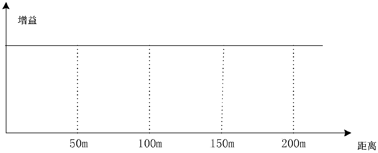
[0039] Gain: In short, it is the magnification, usually the ratio of the signal output to the signal input of a system. The amplifier gain is the logarithm of the ratio of the output power of the amplifier to the input power, which is used to indicate the degree of power amplification, and also refers to voltage or current. of magnification.

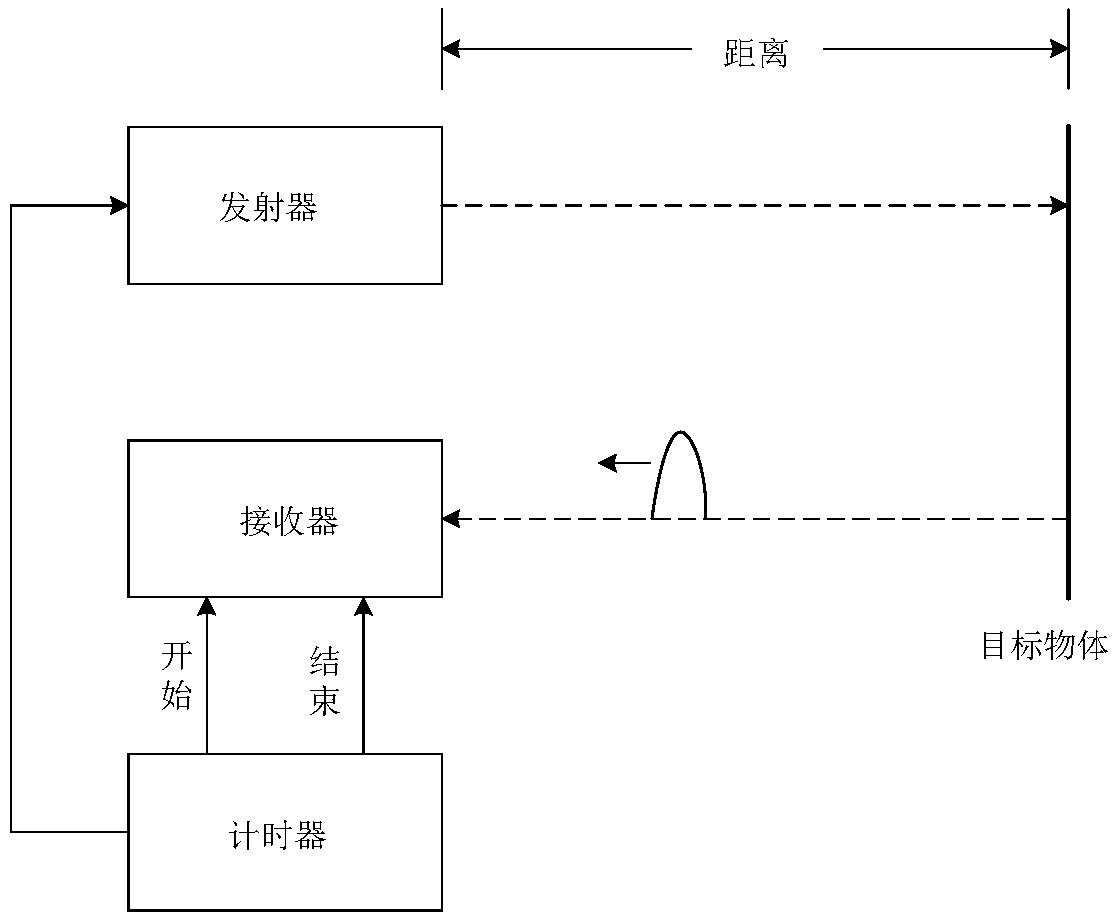
[0040] figure 1 Schematic diagram of the working principle of lidar ...


PUM


Abstract

The invention relates to a laser radar ranging system. The system comprises a variable gain amplifier, a converter and a controller, the variable gain amplifier is connected with the converter, and the converter is connected with the controller; wherein the controller is used for determining the distance measurement distance between the target object and the optical receiver according to an outputsignal of the converter, and adjusting the gain of the variable gain amplifier according to the distance measurement distance. The controller adjusts the variable gain amplifier to reduce the gain ina short distance and adjusts the variable gain amplifier to increase the gain in a long distance, so that the amplitude of an optical signal detected by the laser radar in long-distance detection isenhanced, the dynamic range of a detection signal of the laser radar is improved, and the distance measurement performance and the distance measurement capability are further improved.

Description

technical field [0001] The invention relates to the field of laser radar, in particular to a laser radar ranging system. Background technique [0002] Lidar is a radar system that emits laser beams to detect characteristic quantities such as the position and speed of targets. Lidar uses laser as the signal source, and the laser emits pulsed laser to target objects such as trees, roads, bridges and buildings on the ground. The pulsed laser hits the target object, causing scattering, and a part of the light wave will be emitted to the receiver of the laser radar. On the basis of the signal reflected by the target object, the relevant information of the target object can be obtained, such as the target distance, azimuth, height, speed and the shape of the object and other parameters. [0003] At present, the use of lidar for ranging is mainly by measuring the flight time of the laser between the target object and the lidar, and according to the flight time and the speed of lig...

Claims


Application Information

Patent Timeline
Patent Type & Authority Applications(China)
IPC IPC(8): G01S17/08G01S7/481
CPCG01S17/08G01S7/481
Inventor 邱纯鑫刘乐天
Owner SUTENG INNOVATION TECH CO LTD
Why Eureka
Try Eureka