
Linear Solid-State Lighting With A Wide Range Of Input Voltage And Frequency Free Of Fire And Shock Hazards
a technology of linear solid-state lighting and led tubes, which is applied in the direction of lighting safety devices, semiconductor devices of light sources, lighting and heating apparatus, etc., can solve the problems of high total cost of ownership, inability to accurately detect ballasts and replace incompatible parts, and complex maintenance. , to achieve the effect of eliminating the risk of electric shock and accurate output led curren
- Summary
- Abstract
- Description
- Claims
- Application Information
AI Technical Summary
Benefits of technology
Problems solved by technology
Method used
Image

Examples
Embodiment Construction
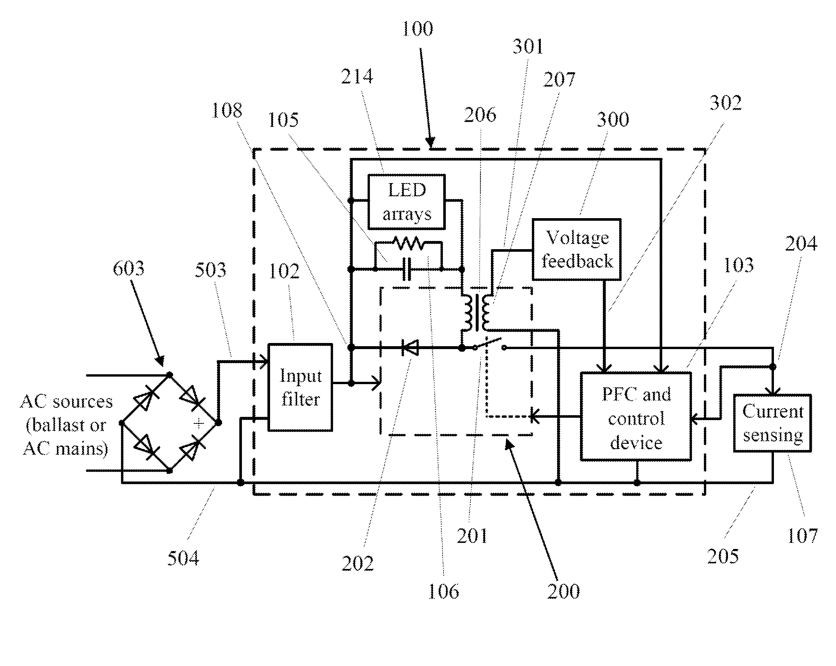
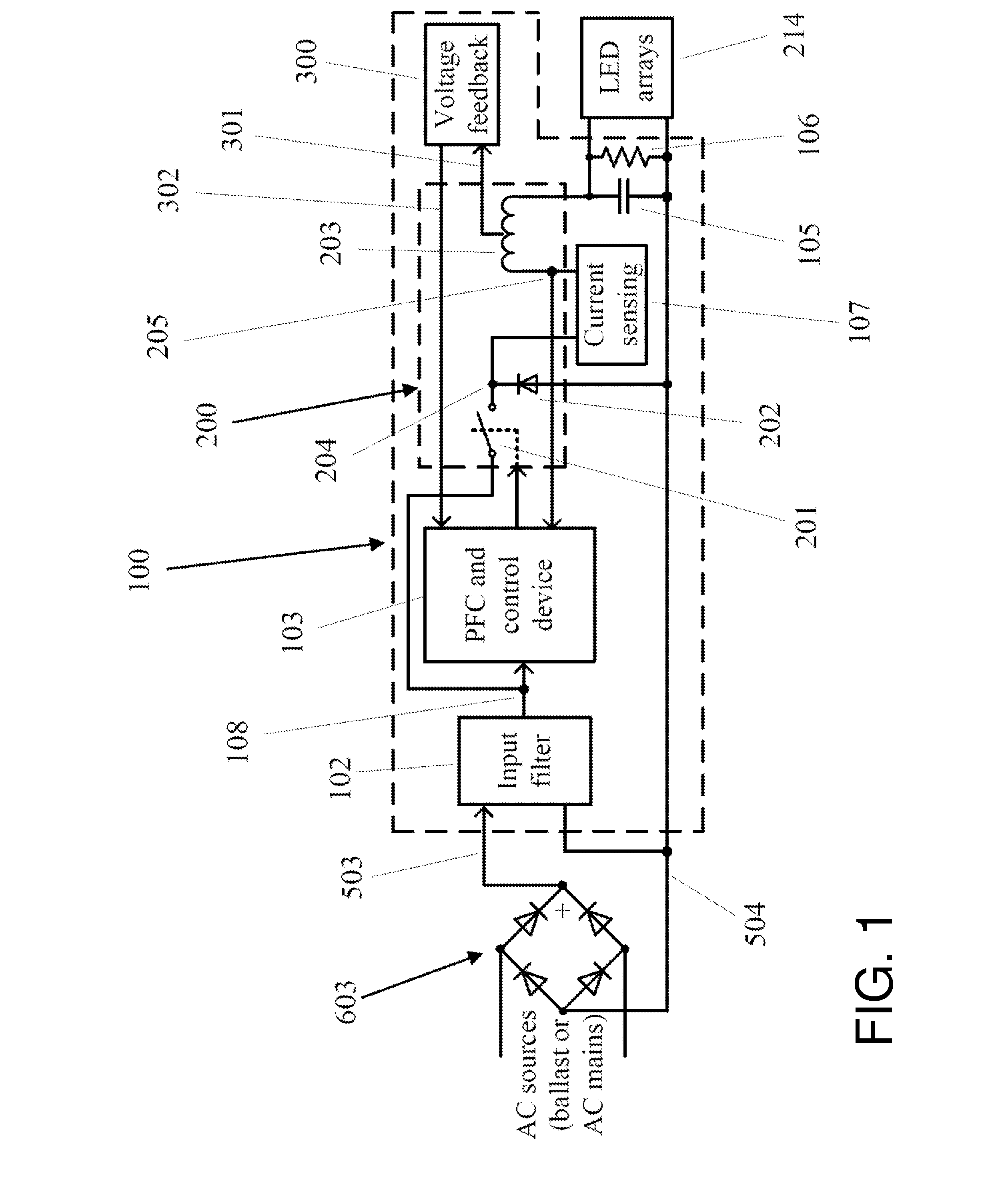
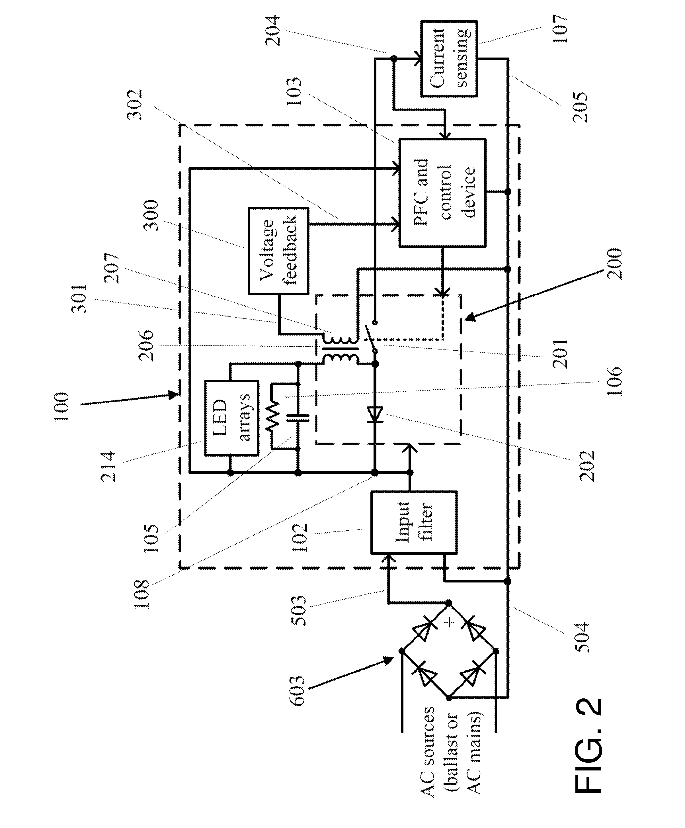
[0023]FIG. 1 is a block diagram of an all-in-one LED driving circuit used in a universal LLT lamp operable with either the AC mains or an electronic ballast according to the present disclosure. A bridge rectifier 603 connecting to an AC source, either the AC mains or an electronic ballast, converts alternating current (AC) into direct current (DC). The all-in-one driving circuit 100 connecting to the bridge rectifier 603 comprises an input filter 102 used to filter the input voltage and to suppress EMI noise created in the all-in-one driving circuit 100, a power factor correction (PFC) and control device 103, a Buck converter 200 in communicating with the PFC and control device 103, an output capacitor 105 in parallel with a resistor 106 connected to the Buck converter 200 to build up an output voltage and to power the LED arrays 214, a current sensing resistor 107, and a voltage feedback module 300 extracting partial energy from the output voltage to sustain the PFC and control dev...
PUM
 Abstract
Description
Claims
Application Information