Apparatus for processing material, and waste container/separating device

a technology for separating devices and apparatuses, applied in the field of apparatuses for processing materials, waste containers/separating devices, collection and conveying of wastes, can solve problems such as occupying space, and achieve the effects of efficient compacting, efficient condensing into the container space, and efficient compacting

Active Publication Date: 2015-08-20
MARICAP OY
View PDF8 Cites 6 Cited by
  • Summary
  • Abstract
  • Description
  • Claims
  • Application Information

AI Technical Summary

Benefits of technology

[0011]The solution according to the invention has a number of important advantages. One advantage, among others, achieved with the solution according to the invention is that a separate separating device is not needed, but instead the waste container functions as an effective separator device and at the same time material can be efficiently compacted in it. In the solution of the invention, therefore, material can be compacted directly in the waste container, which is preferably formed to be a container of the mobile freight container type. By arranging a wall in the container space in the waste container/separating device, which wall guides the material being fed in into the operating range of a press, an effective solution is achieved for compressing material and compacting it, i.e. condensing it, in the container space. The wall also prevents the return or displacement of compressed material in the container space backwards past the press. The wall is thus configured to prevent the passage of compressed material in the opposite direction to the compression direction, in which case material can be condensed into the container space efficiently with the press. By using a movable part that has a support surface, the wall can be supported when the press is operated. In this case material can be efficiently compacted into the container part better than before. The movable part can be a part of the press device, e.g. a moving frame of the press

Problems solved by technology

A problem in prior-art combinations of a waste container and separating device, more particularly in horizontal separator containers, is

Method used


Image

  • Apparatus for processing material, and waste container/separating device
  • Apparatus for processing material, and waste container/separating device
  • Apparatus for processing material, and waste container/separating device

Examples


second embodiment

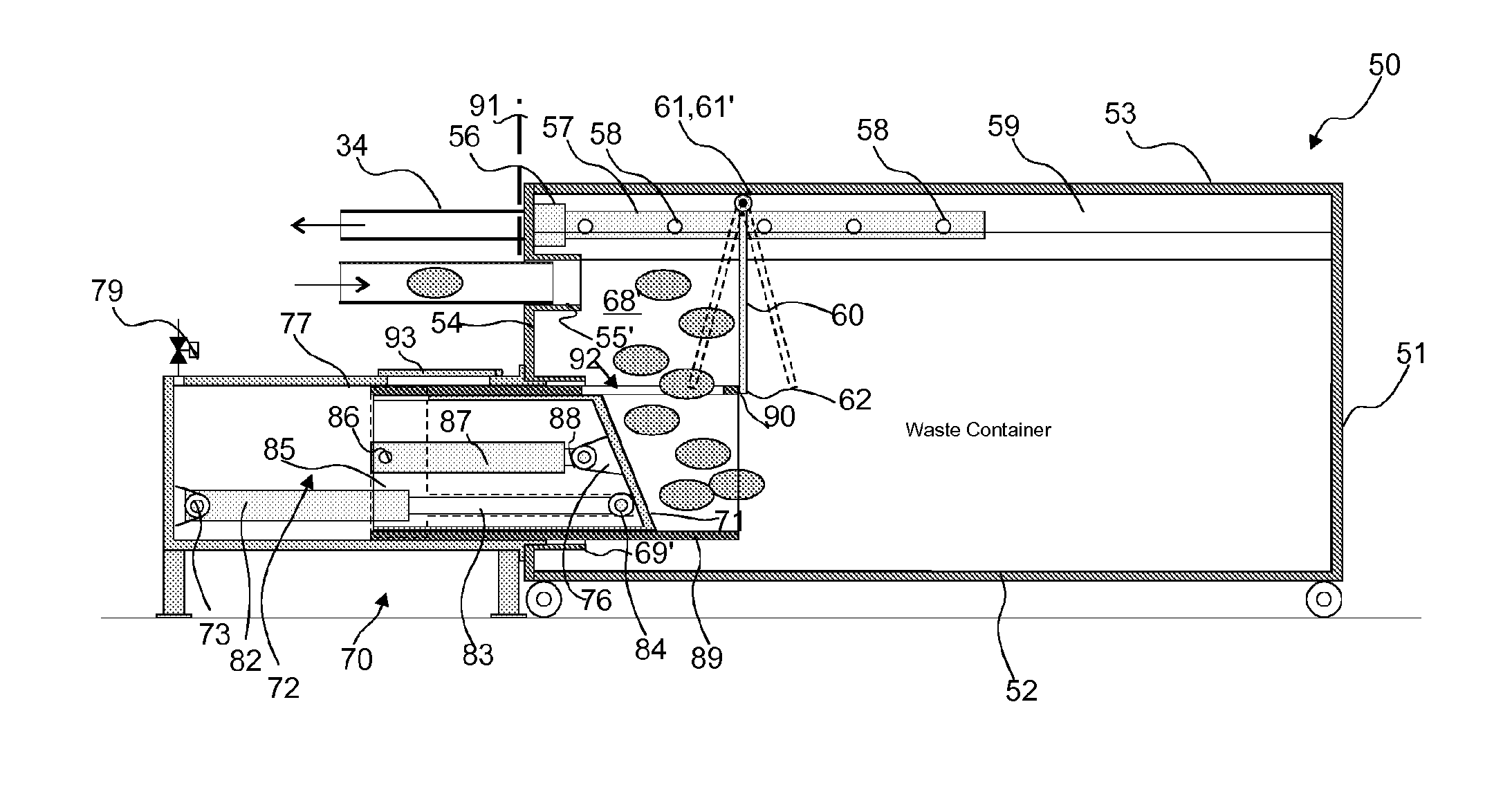
[0050]FIGS. 9 and 10 present the apparatus according to the invention, in which a movable part 89 is arranged in connection with the press device / compactor device 70, which movable part when extended settles in the proximity of the bottom part 62 of the wall 60 arranged in the container space 68 of the waste container / separating device 50 and if necessary supports the wall 60 preventing its essential movement, such as a rotary movement around the axis 61′, towards the wall 54 on the side of the inlet aperture 55. The movable part 89 has a support surface 90, against which the bottom part 62 of the wall 60 can be supported. In the embodiment of FIGS. 9 and 10 the drive apparatus 72 of the press device / compactor device 70 comprises a two-phase arrangement, in which a first drive device 82, 83 is arranged to move the movable part 89 as well as a second drive device 87, 88 and the compression means 71 connected to it into a second position, and from which second position the compression...

third embodiment

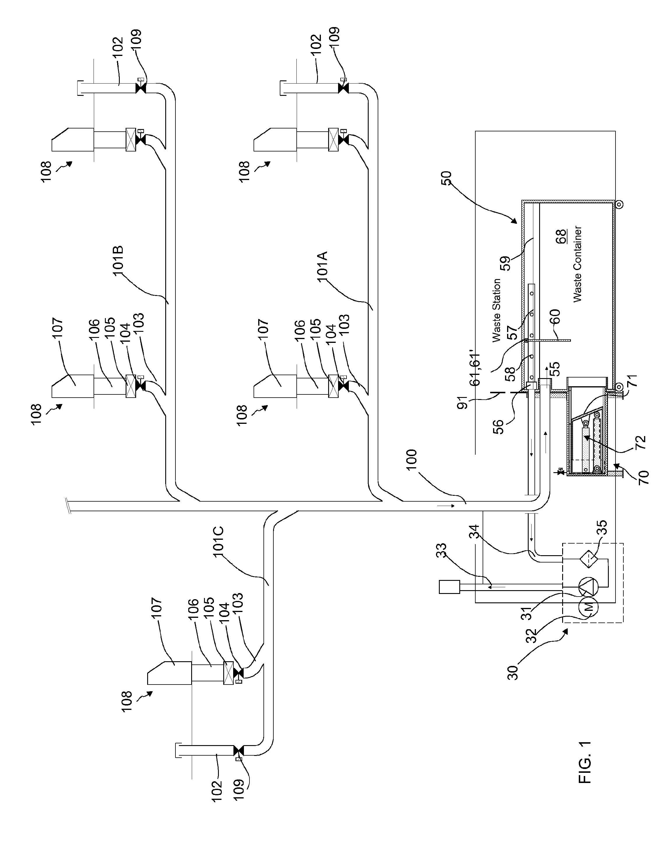
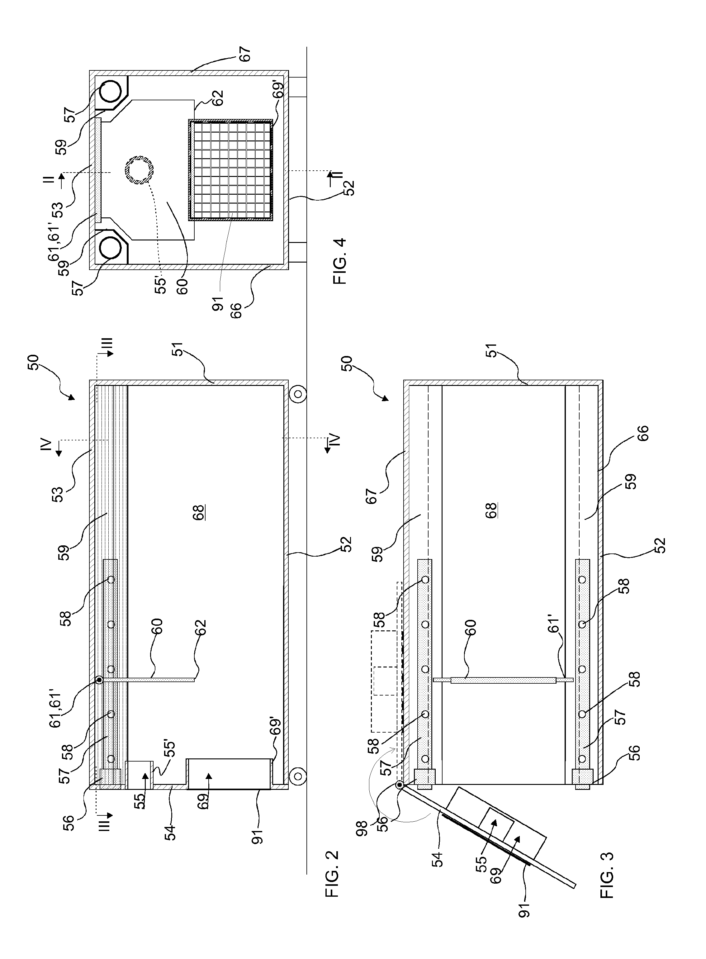
[0052]FIGS. 11-14 further present the invention. Likewise, FIGS. 11-14 present the bringing of a waste container / separating device 50 and connection of it in connection with a press device / compactor device 70 as well as a conveying pipe 100 and a channel 34 of a partial-vacuum generator. In FIG. 11 the waste container / separating device 50 is moved towards the press / compactor. The joint part 80 of the press / compactor device 70 and the end 100 of the conveying pipe as well as the end of the suction channel 34 are arranged in a supported manner in such a way that the necessary joints form, or are formed, when the waste container / separating device 50, the counterparts on it, the press aperture 69, inlet aperture 55 and connection 56 are brought against the joint part 80 and the end 100 of the conveying pipe and the end of the suction channel 34. According to one embodiment the hatch 91 is arranged to cover the aperture 69, which hatch is displaced from the position of FIG. 11 upwards in...

fourth embodiment

[0058]FIGS. 15-22 present the apparatus according to the invention, in which a movable part 89 is arranged in connection with the press device / compactor device 70, which movable part when extended settles in the proximity of the bottom part 62 of the wall 60 arranged in the container space 68 of the waste container / separating device 50 and if necessary supports the wall 60 preventing its essential movement, such as a rotary movement around the axis 61′, towards the wall 54 on the side of the inlet aperture 55. The movable part 89 has a support surface 90, against which the bottom part 62 of the wall 60 can be supported. In the embodiment of the figures the drive apparatus 72 of the press device / compactor device 70 comprises a two-phase arrangement, in which a first drive device 82, 83 is arranged to move a movable part 89 as well as a second drive device 87, 88 and the compression means 71 connected to it into a second position, and from which second position the compression means i...


PUM

PropertyMeasurementUnit
Timeaaaaaaaaaa
Heightaaaaaaaaaa
Vacuumaaaaaaaaaa

Abstract

Apparatus for processing material in connection with a pneumatic material conveying system, which apparatus includes a waste container/separating device, into which material is configured to be conducted from a conveying pipe of the pneumatic material conveying system via an inlet aperture and which is configured to be connected to a device for achieving a partial vacuum. The apparatus further includes a press device/compactor device, which is arranged to act on the material (w) conducted into the waste container/separating device, via at least one aperture formed in the container, and that at least one wall that is transverse with respect to the input direction of the material is arranged in the container space of the waste container/separating device, which wall is configured to guide the material into the operating range in the container space of the compression device of the press device/compactor device. The invention also relates to a waste container/separating device.

Description

BACKGROUND OF THE INVENTION[0001]The object of the invention is an apparatus as defined in the preamble of claim 1.[0002]The object of the invention is also a waste container / separating device as defined in claim 16.[0003]The object of the invention is also a press / compactor device, as defined in the preamble of claim 27, which can be connected to the waste container / separating device according to the invention.[0004]The invention relates generally to material conveying systems, such as to partial-vacuum transporting systems, more particularly to the collection and conveying of wastes, such as to the conveying of household wastes.[0005]Systems wherein wastes are conveyed in piping by means of a pressure difference or suction are known in the art. In these, wastes are conveyed long distances in the piping by sucking. It is typical to these systems that a partial-vacuum apparatus is used to achieve a pressure difference, in which apparatus negative pressure is achieved in the conveyin...

Claims


Application Information

Patent Timeline
IPC IPC(8): B65F3/14B65F3/20B30B9/30
CPCB65F3/143B65F3/201B30B9/3042B30B9/301B30B9/3057B65F1/105B65F1/1405B65F5/005B65G53/60
Inventor SUNDHOLM, GORAN
Owner MARICAP OY
Why Eureka
Try Eureka