Air-curtain device

Inactive Publication Date: 2015-08-27
THERMOSCREENS
10 Cites 0 Cited by

AI-Extracted Technical Summary

Problems solved by technology

Such a flow of air impedes mixing of the air masses on either side of the opening.
This results in a red...

Method used

[0014]The main air driving means 3 of the present embodiment is elongate, extends along the top of the doorway 2, and comprises a blower fan, and provides a main air-curtain 4 which extends from the top of the doorway 2 to the floor. As can be seen from FIG. 1, this prevents or reduces airflow 9 from outside the doorway 2 from passing through the doorway 2 into the interior of the building in which the doorway 2 is formed. Thus a substantially reduced airflow 10 occurs into the building. However, as seen in FIG. 2, because of the gap g, the main air-curtain 4 is not flush with the doorway 2, and at each side of the doorway 2, at end of the air-curtain device 1, air from outside the building can enter the building while bypassing the main air-curtain 4. For this reason the lateral air driving means 5, each comprising a blower fan, are provided at each end of the air-curtain device 1 above the doorway 2, which each provide a lateral airstream at one of the sides of the doorway 2, to form lateral air-curtains 6 at each side of the main air-curtain 4. The lateral air curtains 6 are also generated above the doorway 2, and specifically, each extends from the plane of the main air-curtain 4 to the wall 7 substantially along the full height of the doorway 2. In this way, the lateral air-curtains 6 close the gap g and prevent or reduce air flow from the outside of the building around the sides of the ma...

Benefits of technology

[0003]According to a first aspect of the invention, there is provided an air curtain device according to claim 1. In accordance with this aspect, provision of lateral air driving means, which deliver an air-curtain which is angled to that of the main air driving means, all...

Abstract

Disclosed is an air-curtain device (1) which can be positioned across the top of an openingsuch as a doorway (2), and comprises main air driving means (3) for providing a main airstream across the opening (2) to form a main air-curtain (4), and lateral air driving means (5) for providing a lateral airstream angled relative to the airstream from the main air driving means (3) to form a lateral air-curtain (6).

Application Domain

Lighting and heating apparatusAir currents for screening

Technology Topic

Image

  • Air-curtain device
  • Air-curtain device
  • Air-curtain device

Examples

  • Experimental program(1)

Example

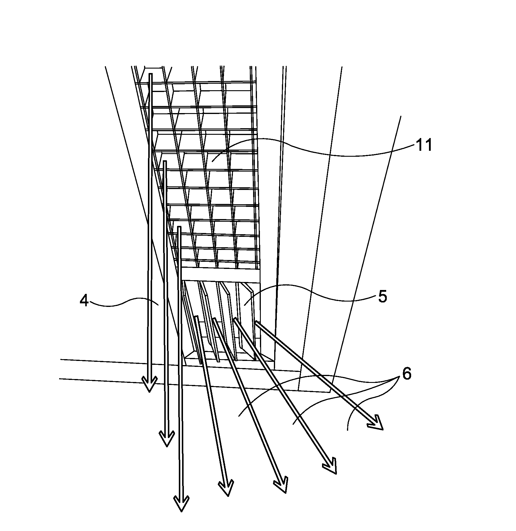
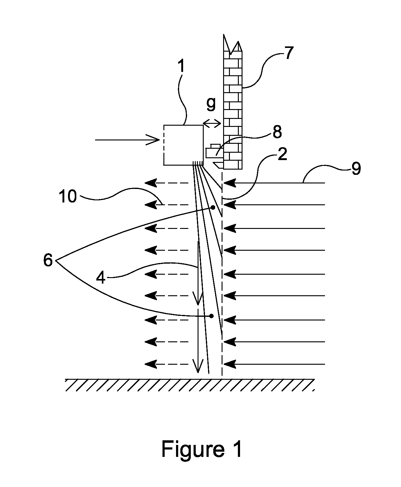
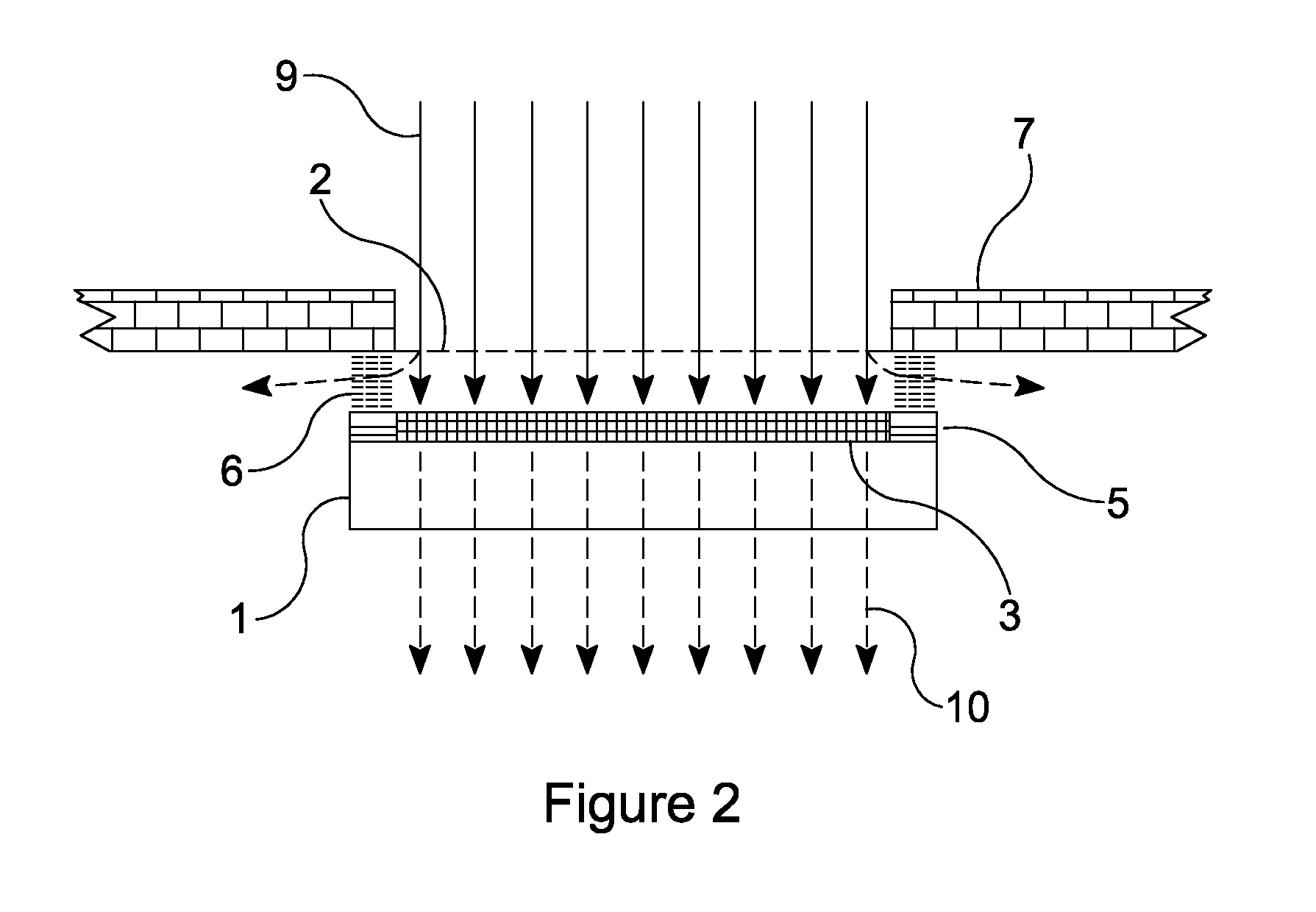
[0011]As shown in FIGS. 1 and 2, the air-curtain device 1 of the first embodiment is positioned across the top of an opening, which in the present embodiment is a doorway 2, and comprises main air driving means 3 for providing a main airstream across the opening 2 to form a main air-curtain 4, and lateral air driving means 5 for providing a lateral airstream angled relative to the airstream from the main air driving means 3 to form a lateral air-curtain 6.
[0012]The opening 2 is formed by a gap in a wall 7. The main air-curtain 4 extends from the air-curtain device 1, which is mounted above the doorway 2, all the way to the opposite edge of the doorway 2, which, in the present embodiment is the floor. The air-curtain device 1 is positioned away from the wall 7 and the doorway 2, to allow a door and the mechanism 8 therefor to be positioned so that the door closes the doorway 2. In the present embodiment, the door is a sliding door, so that the air driving means of the air-curtain device can be positioned at the same height as the top of the doorway 2.
[0013]However, the provision of the door and mechanism 8 means that a gap g is provided between the doorway 2 and the air-curtain device 1.
[0014]The main air driving means 3 of the present embodiment is elongate, extends along the top of the doorway 2, and comprises a blower fan, and provides a main air-curtain 4 which extends from the top of the doorway 2 to the floor. As can be seen from FIG. 1, this prevents or reduces airflow 9 from outside the doorway 2 from passing through the doorway 2 into the interior of the building in which the doorway 2 is formed. Thus a substantially reduced airflow 10 occurs into the building. However, as seen in FIG. 2, because of the gap g, the main air-curtain 4 is not flush with the doorway 2, and at each side of the doorway 2, at end of the air-curtain device 1, air from outside the building can enter the building while bypassing the main air-curtain 4. For this reason the lateral air driving means 5, each comprising a blower fan, are provided at each end of the air-curtain device 1 above the doorway 2, which each provide a lateral airstream at one of the sides of the doorway 2, to form lateral air-curtains 6 at each side of the main air-curtain 4. The lateral air curtains 6 are also generated above the doorway 2, and specifically, each extends from the plane of the main air-curtain 4 to the wall 7 substantially along the full height of the doorway 2. In this way, the lateral air-curtains 6 close the gap g and prevent or reduce air flow from the outside of the building around the sides of the main air-curtain 4. As the lateral air driving means 5 themselves do not extend to the wall 7 of the building, the door and mechanism therefor 8 can still operate normally. If the lateral air driving means 5 were to extend all the way from the main air driving means to the wall, while this would allow a straight flow of air from the lateral air driving means to the floor to close the gap between the doorway 2 and the main air-curtain 4, this would not allow the door and mechanism therefor 8 to operate normally.
[0015]In an alternative embodiment, instead of a separate fan, which may be an auxiliary fan positioned behind the lateral airstream outlets to supplement the air volume flow rate of the lateral air-curtains, a single fan, or multiple fans, may be provided, housed and ducted so as to provide/drive air for both the main and lateral air-curtains 4, 6. The main and lateral air-driving means 3, 5 may therefore have one or more common air blower fans. Therefore in this embodiment, the main and lateral air-driving means 3, 5 may be the same, and different parts of the air flow generated may be guided/driven to form the main and lateral air flows.
[0016]As shown in FIG. 3, the main air driving means comprises an outlet grille 11, which is elongate and extends across the top of the opening, and uses this outlet grille 11 to produce an airstream which is substantially planar, and substantially parallel to the doorway 2, i.e. vertical in the present embodiment. The lateral air driving means 5 forms the lateral airstream by making use of a plurality of adjustable vanes which are arranged across the outlet of the lateral air driving means 5 in a direction transverse to the plane of the airstream. The adjustable vanes are shown more clearly in FIG. 4. In FIG. 4, it can be seen that four vanes 12, 13, 14, and 15 are provided. These vanes are angled differently to one another. A divergent airstream is provided, rather than the planar airstream of the main air driving means 3. In this way, the gap g between the main air-curtain 4 and the wall 7 of the building can be closed, as different parts of the lateral air-stream flow in slightly different directions from the top of the doorway 2 to the bottom of the doorway 2, but also towards the sides of the doorway 2. The airstream between one part of the body 17 of the lateral air driving means 5 and the first vane 12 is directed almost parallel to the main air-curtain 4 to extend to the floor. The airstream between the first and second vanes 12 and 13 is angled more, so as to extend to a lower part of the wall 7 surrounding the doorway 2. The airstream between the second and third vanes 13 and 14 is angled more, so as to extend to a part midway up the wall 7 surrounding the doorway 2. The airstream emanating from between the third and fourth vanes 14 and 15 is angled yet more, so as to be directed to an upper part of the wall 7, while the airstream emanating from between the fourth vane and the adjacent part of the lateral air driving means 15 and 16 is angled yet further so as to be directed at an uppermost area of the wall 7 surrounding the doorway 2. In this way, the divergent air flow from the lateral air driving means 5 forms a wall of moving air that substantially fills the gap between the air-curtain device 1 and wall 7 surrounding the doorway 2.
[0017]In the present embodiment, a lateral air driving means 5 is provided at each end of the elongate air-curtain device 1. Both lateral air driving means 5 function in the same way as described above. Although four vanes have been shown, it will be apparent that any number of vanes as appropriate for the particular gap g and height of doorway 2 can be employed to provide the boundary lateral air-curtain.
[0018]FIG. 5 shows an alternative embodiment according to the invention. In this embodiment, only the vanes of the lateral air driving means have been changed; the rest of the device is as described above. In the present embodiment, instead of a plurality of independently adjustable vanes, a single outlet grille is provided in the lateral air driving means. This outlet grille is angled relative to the grille of the main air driving means; specifically, while providing an air-curtain generally downwards, it is angled towards the wall surrounding the doorway. Thus, the airstream from the lateral air driving means is angled to the main airstream, and provides a lateral air curtain which at least partially closes the gap between the air-curtain device and the wall surrounding the opening, while having the advantage over the vanes of the first embodiment of being simpler to configure and install.
[0019]In both embodiments described above, the lateral air driving means is relatively short in extent, compared with the main air driving means, which extends substantially, if not completely, across the top of the opening.

PUM

no PUM

Description & Claims & Application Information

We can also present the details of the Description, Claims and Application information to help users get a comprehensive understanding of the technical details of the patent, such as background art, summary of invention, brief description of drawings, description of embodiments, and other original content. On the other hand, users can also determine the specific scope of protection of the technology through the list of claims; as well as understand the changes in the life cycle of the technology with the presentation of the patent timeline. Login to view more.

Similar technology patents

Methods and devices for analyte sensing in potential spaces

ActiveUS20170281062A1EffectiveFaster insulin deliveryCatheterSensorsSkin temperaturePeritoneal membrane
Owner:THERANOVA LLC

Anti-breakage anchor rod

Owner:CHONGQING UNIV

Red ginseng extract pellet and preparation method thereof

InactiveCN102462715AEffectiveSmall fluctuations in blood concentrationNervous disorderImmunological disordersPharmaceutical preservativesGINSENG EXTRACT
Owner:JF PHARMALAND TECH DEV

External preparation of essential oil from Bupleurum root

InactiveCN101224227AEffectiveConvenient for clinical selectionAntipyreticAerosol deliverySolventChemistry
Owner:JF PHARMALAND TECH DEV

Novel foundation strengthening method and structure

InactiveCN104005433ASimple technical measuresEffectiveFoundation repairRebarContact position
Owner:上海纺织建筑设计研究院有限公司

Classification and recommendation of technical efficacy words

Why Eureka
Try Eureka