Light detection system and method

a light detection and coded light technology, applied in the field of illumination and coded light illumination systems, can solve the problems of slow read-out capacity, low light sensitivity, and inability to provide information about the spatial footprin

Active Publication Date: 2015-09-03
SIGNIFY HLDG BV
View PDF10 Cites 53 Cited by
  • Summary
  • Abstract
  • Description
  • Claims
  • Application Information

AI Technical Summary

Benefits of technology

[0005]It is an object of the present invention to overcome the above mentioned problems, and to provide an improved light detection system and a method capable of detecting CL embedded into a light output of light sources in a manner that allows detection of the embedded data (e.g. unique identifiers) sent by the different light sources being present in a 2D scene.

Problems solved by technology

These, however, only provide point measurements, which is cumbersome in the presence of multiple Coded Light sources and does not provide information about the spatial footprint, i.e. the geometric intensity distribution and spatial localization of light contribution from each individual light source in a scene.
This approach, however, results in very slow read-out capacity and suffers from low light sensitivity.

Method used


Image

  • Light detection system and method
  • Light detection system and method
  • Light detection system and method

Examples


Embodiment Construction

[0042]The present invention will now be described more fully hereinafter with reference to the accompanying drawings. The below embodiments are provided by way of example so that this disclosure will be thorough and complete, and will fully convey the scope of the invention to those skilled in the art. Like numbers refer to like elements throughout.

[0043]In the following, we consider a scenario in which Coded Light is used to transmit light source identifiers by modulating each light source with a characteristic frequency selected from a predetermined set of candidate frequencies. The scope of the invention, however, is by no means limited to this scenario. It should be appreciated that the detection of a sequence of different modulation frequencies per lamp, but also the simultaneous detection of multiple modulation frequencies per lamp can respectively be considered as temporally separated combinations or as linear combination of detection results from single-frequency modulations...


PUM


Abstract

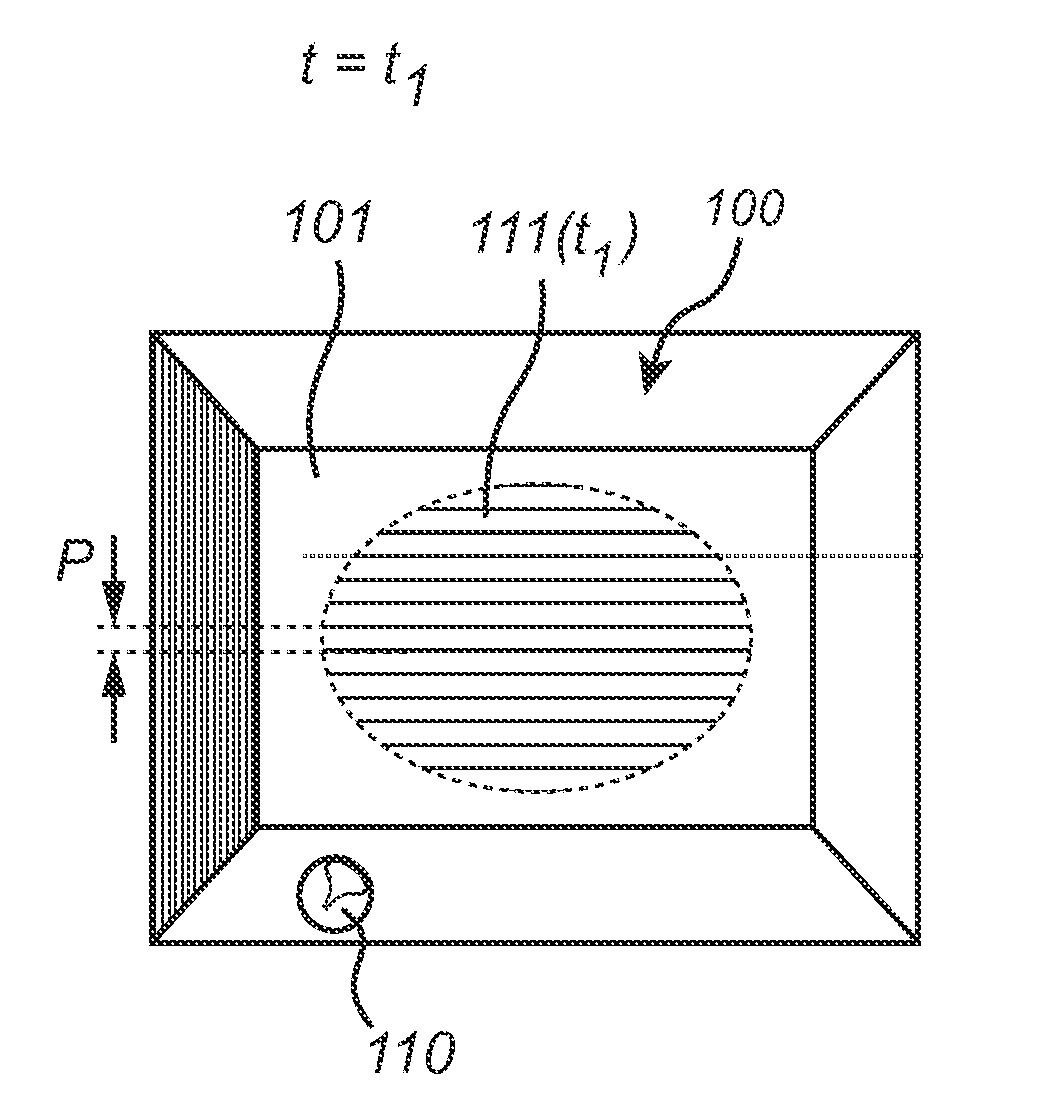
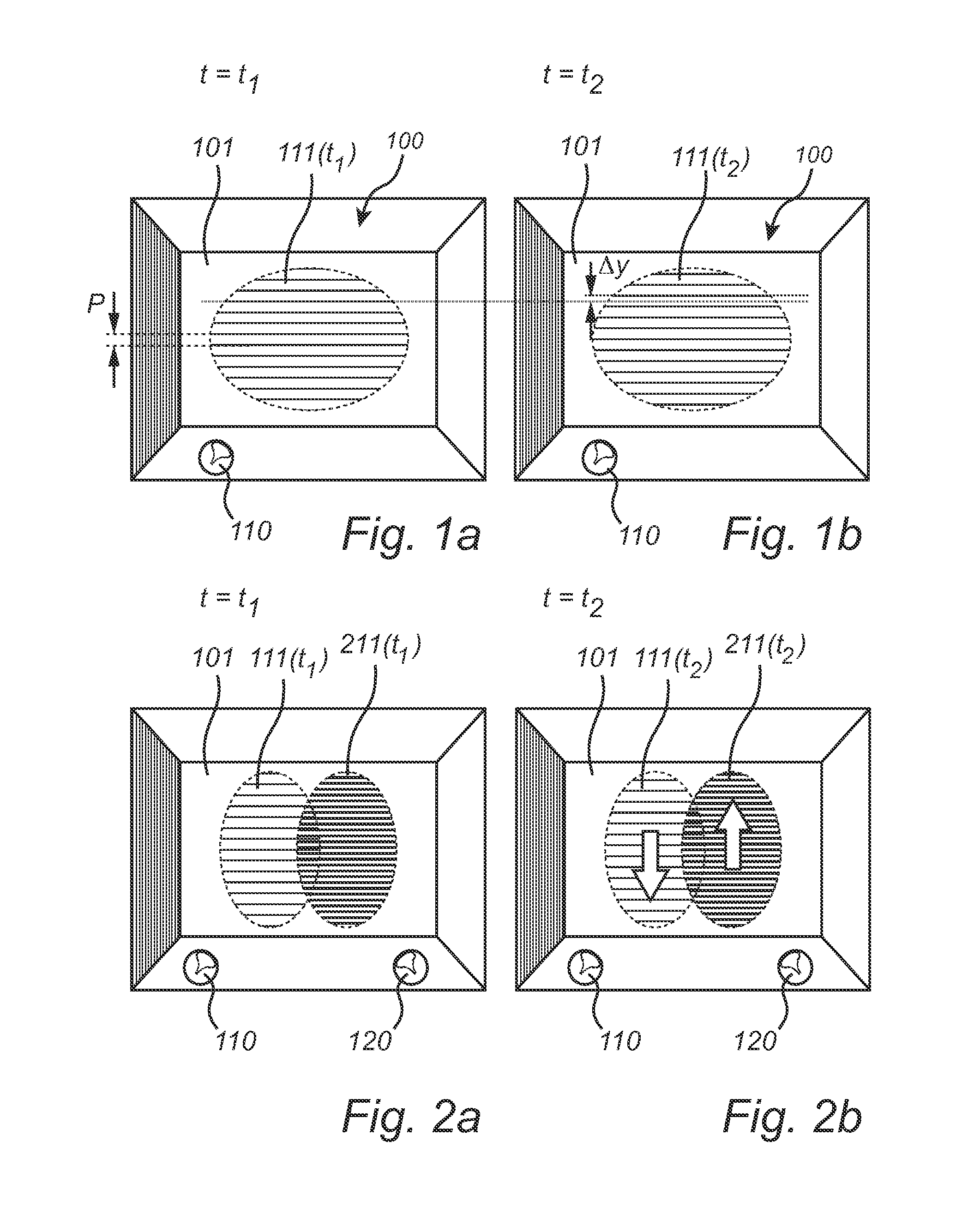
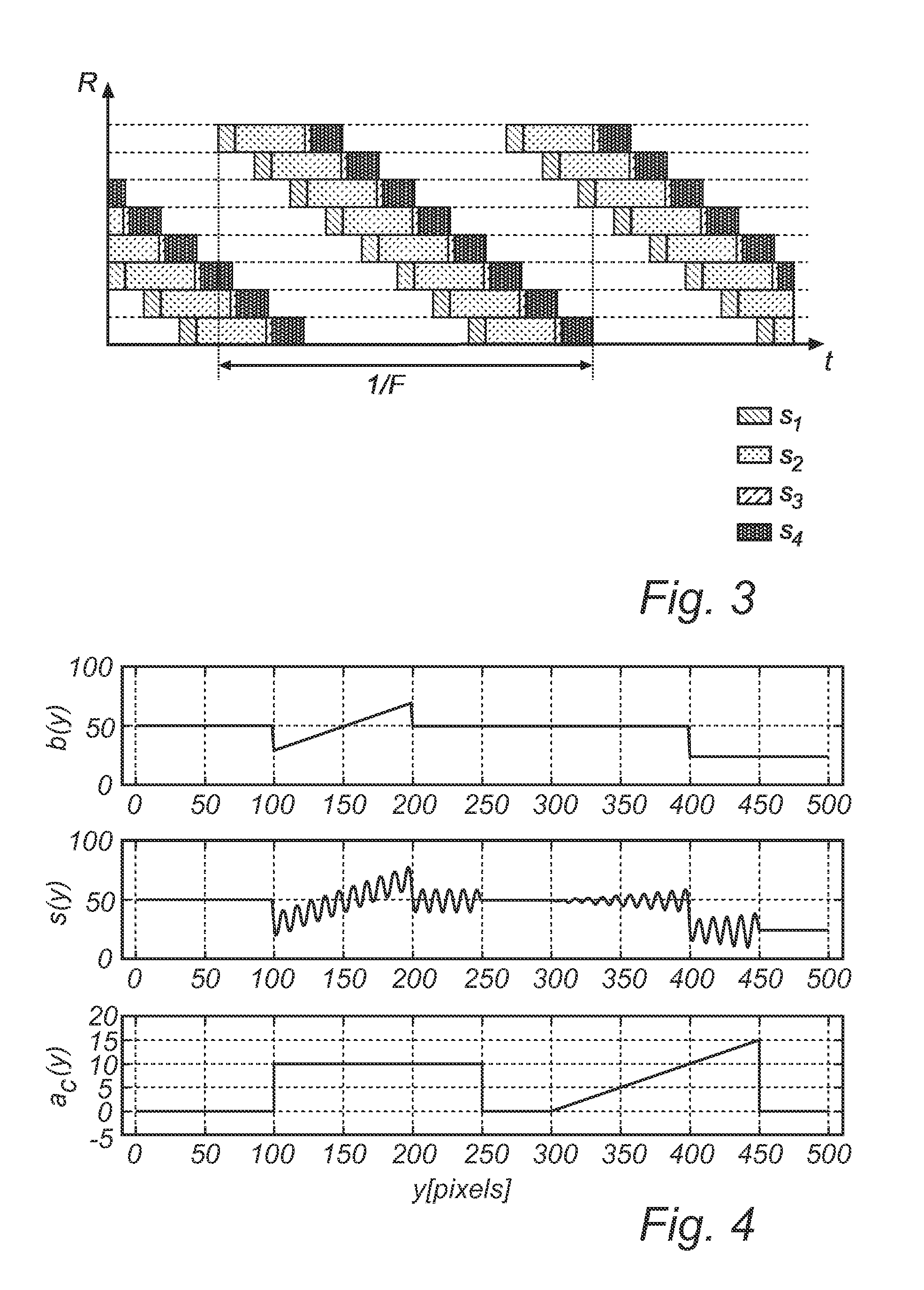
There is provided a method for detecting modulated light comprising: receiving a set of images acquired by means of a rolling shutter camera having image acquisition settings comprising a frame rate, fframe, and a line rate, fline; identifying in consecutive frames of said images—a pattern governed by the ratio between a modulation frequency, fc, of a modulated light source and the line rate, fline, and—between consecutive frames a spatial shift of said pattern governed by the ratio between said modulation frequency fc, and said frame rate, fframe; and providing based on said pattern and spatial shift thereof, an estimate of the modulated light amplitude from said light source.

Description

FIELD OF THE INVENTION[0001]The present invention relates generally to the field of illumination, Coded Light illumination systems, and more particularly to a system and method for detecting modulated light in the light output of such illumination systems.BACKGROUND OF THE INVENTION[0002]Coded Light (CL) is visible light that carries embedded information which is encoded in a form such that the presence of the additional information is imperceptible by the human visual system. Generally, this means that the encoding is based on the use of high-frequent modulations of the light intensity. The encoded information can be anything, from a lamp-specific identifier to an HD-TV signal. The disclosed invention is primarily focused, but not limited to, the use of CL for the identification of different light sources, as well as the identification and quantification of their separate light contributions, or footprints, in the illuminated scene. The detection of lamp-specific identifiers facili...

Claims


Application Information

Patent Timeline
Patent Type & Authority Applications(United States)
IPC IPC(8): H04B10/116H05B44/00
CPCH04B10/116H05B45/20H05B47/125Y02B20/40H04B10/114
Inventor MUIJS, REMCO THEODORUS JOHANNESDE BRUIJN, FREDERIK JANGRITTI, TOMMASONIJSSEN, STEPHANUS JOSEPH JOHANNESFERI, LORENZO
Owner SIGNIFY HLDG BV
Why Eureka
Try Eureka