Nasal Dilator With Means To Direct Resilient Properties

a dilator and resilient technology, applied in the field of dilating external tissue, can solve the problems of affecting breathing, sleep disturbance, irregularities and general discomfort, and typically having limited properties, so as to prevent one or more material separations, extend or increase the tissue engaging surface area

Inactive Publication Date: 2015-09-10
CORBETT LAIR INC
View PDF11 Cites 44 Cited by
  • Summary
  • Abstract
  • Description
  • Claims
  • Application Information

AI Technical Summary

Benefits of technology

[0020]An interior material separation may form a flap capable of separating or vertically protruding, in part, from the truss when the dilator is flexed across the nose of a wearer. Similarly, an exterior material separation may form a horizontal protrusion, also capable of separating, in part, from the truss when the dilator is flexed across the nose of a wearer. In either case, said separation or vertical protrusion changes the angle of focused spring biasing forces, at least in part, and thus shifts or transforms at least some of said forces from primarily peel and tensile forces to primarily shear forces. Said change in angle further redistributes or imparts said transformed forces to tissue engaging surface areas extending beyond the material separation. Thus, spring biasing forces may be distributed to the potentially larger surface area of the dilator end regions, as opposed to a greater delaminating tendency, such as that from peel forces, being imparted to a smaller surface area. Said potential larger surface area is as a result of the configuration of the end regions of the truss and / or the configuration of the respective layers of the dilator. The effect of material separations can lessen overall delaminating forces without reducing the spring biasing force of the dilator, in that shear forces are more easily withstood by the tissue engaging adhesives typically disposed on the tissue engaging surfaces of the dilator. Accordingly, a lesser amount of adhesive and / or less aggressive adhesive (and thus less costly) disposed on the tissue engaging surfaces of the dilator would, in addition, be more comfortable to the user and more easily removed from the tissue so engaged. An opposing pair of said material separation may be spaced apart along the longitudinal centerline of the truss.
[0023]The preferred embodiments of the present invention further include a truss with means for horizontally aligning the dilator to the nose of a wearer comprising a positioning aid located at the intermediate region forming a separation, projection or other index marker; means to spread the spring biasing force of resilient layer to a greater, primarily lateral, surface area of dilator, and means to prevent one or more material separations from separating in part from the truss. This latter means may also be used to extend or increase the tissue engaging surface area of the truss.

Problems solved by technology

A portion of the human population has some malformation of the nasal passages which interferes with breathing, including deviated septa and swelling due to allergic reactions.
Blockage of the nasal passages as a result of malformation, symptoms of the common cold or seasonal allergies are particularly uncomfortable at night, and can lead to sleep disturbances, irregularities and general discomfort.
Said material, such as a spunlaced polyester nonwoven fabric, typically has properties which permit limited, primarily plastic and somewhat elastic deformation within the thickness thereof.
Constructing a device with less than 10 grams of spring biasing force in order to mitigate delaminating peel forces may not provide suitable stabilization to, or dilation of, nasal outer wall tissues.
Over-engineering the dilator by using a more aggressive adhesive, a greater amount of adhesive, or greater adhesive surface area in order to withstand greater spring biasing force increases the likelihood of user discomfort during use and damage to the tissue upon removal of the device.
Additionally, a dilating spring biasing force of 40 grams or more could, in and of itself, be uncomfortable for most users.
However, the fabrication process wastes more material than that which is devoted to the resilient member itself.
However, arriving at a suitable material and fabricating a resilient member that flexes in opposing directions—both parallel and perpendicular to its long axis—is problematic.

Method used


Image

  • Nasal Dilator With Means To Direct Resilient Properties
  • Nasal Dilator With Means To Direct Resilient Properties
  • Nasal Dilator With Means To Direct Resilient Properties

Examples


Embodiment Construction

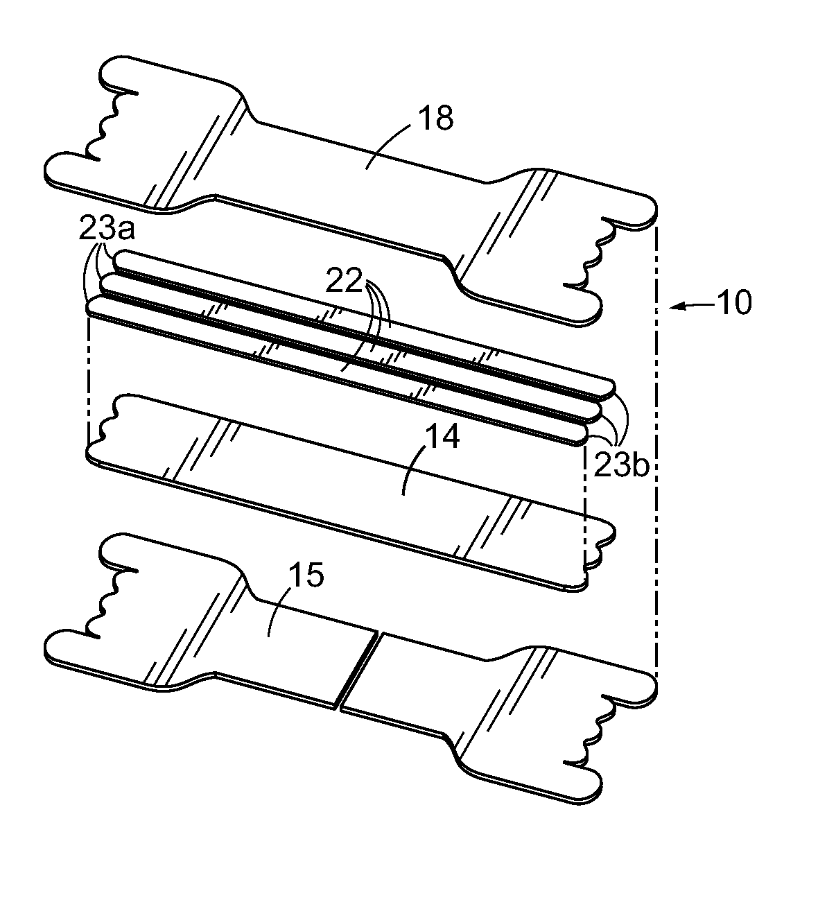
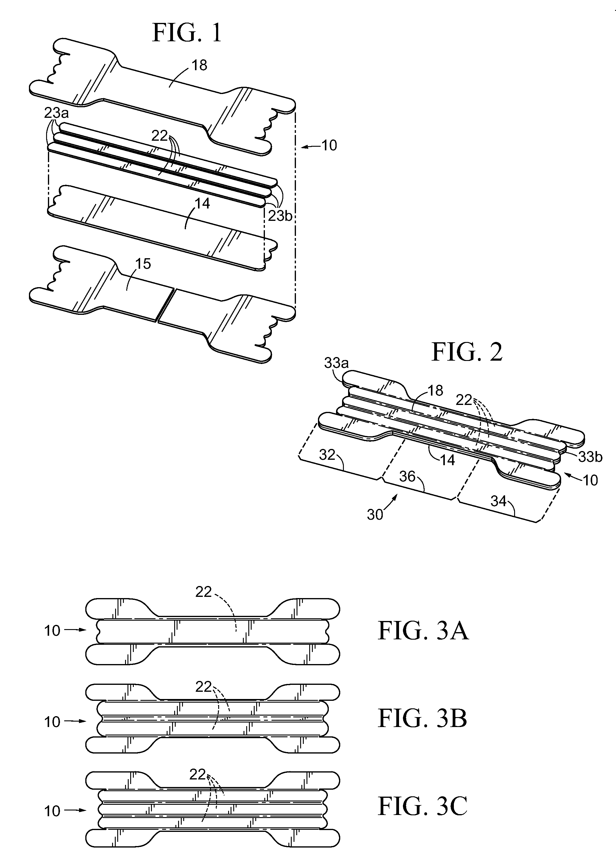
[0062]An embodiment of a nasal dilator, 10, in accordance with the present invention is illustrated in FIG. 1. Dilator 10 comprises a vertical laminate of material layers including: a base layer composed of at least one base member, 14, including components thereof; a resilient layer comprised of at least one resilient member, 22, including components thereof; and a cover layer composed of at least one cover member, 18, including components thereof. A protective layer of release paper liner, 15, removably covers any exposed adhesive from any layer preliminary to use of dilator 10 on the nose of a wearer. The periphery of release liner 15 may correspond to the periphery of dilator 10 or a periphery exceeding one or more dilators 10. The components or layers of dilator 10 are preferably aligned along their longitudinal centerlines.

[0063]The preferred material for the base and cover layers is from a group of widely available flexible nonwoven synthetic fabrics that allow the skin on us...


PUM


Abstract

A nasal dilator comprises a laminate of vertical layers that form a unitary, or single body, truss having horizontal regions adapted to engage outer wall tissues of first and second nasal passages and to traverse the bridge of a nose therebetween. When in use the dilator acts to stabilize and / or expand the nasal outer wall tissues and prevent said tissues from drawing inward during breathing. The dilator includes multiple parallel resilient members or a resilient member having a plurality of component spring fingers extending from a common center. The dilator may further include material separations, or discontinuity of shape of material, formed in at least one region of the truss and extending through at least one layer of the dilator.

Description

RELATED APPLICATIONS[0001]The present application is a Continuation of U.S. Non Provisional patent application Ser. No. 13 / 437,929 filed 3 Apr. 2012. Non Provisional patent application Ser. No. 13 / 437,929 is a Continuation In Part of U.S. Non Provisional patent application Ser. No. 13 / 206,462, filed 9 Aug. 2011, now U.S. Pat. No. 8,444,670. Non Provisional patent application Ser. No. 13 / 206,462 is a Continuation of U.S. Non Provisional patent application Ser. No. 12 / 106,289 filed 19 Apr. 2008, now U.S. Pat. No. 8,062,329. Non Provisional patent application Ser. No. 12 / 106,289 claims priority benefit from Provisional Patent Application No. 60 / 913,271 filed 21 Apr. 2007.FIELD OF THE INVENTION[0002]The present invention relates to apparatus and methods of dilating external tissue. As disclosed and taught in the preferred embodiments, the tissue dilator devices are particularly suitable for use as external nasal dilators for supporting, stabilizing, and dilating nasal tissues adjacent a...

Claims


Application Information

Patent Timeline
Patent Type & Authority Applications(United States)
IPC IPC(8): A61F5/08
CPCA61F5/08
Inventor IERULLI, JOSEPH V.
Owner CORBETT LAIR INC
Why Eureka
Try Eureka