H2O Cilia Head Swab

Active Publication Date: 2015-09-17
PAGAN BENIAMINO
17 Cites 6 Cited by

AI-Extracted Technical Summary

Problems solved by technology

When water is trapped in the ear canal, bacteria that normally inhabit the skin and ear canal multiply, causing infection of the ear canal.
If left untreated, complications resulting from swimmer's ear may include:Hearing loss.
Diabetics and older adults are at higher risk for such dangerous complications.
However, common swabs cannot be inserted inside the ears deeply enough to remove the water effectively.
And when they are forced inside the ear, the cause pain...

Benefits of technology

[0035]In essence, the present invention relates to a hydrophilic swab comprised of microcilios to transport water out of the ear canal in an “osmotic” fashion. The hydrophilic material constituting the cilia are intended to act as “micro water suction fingers”. The cilia in this swab are “hairlike” structures that avoid the laceration or damaging of the ear drum. This product also features a gyratory mechanism for enabling the insertion of the cilia into the ear canal and a tiny window or indicator located nearby the cilia capsule (in the man...

Abstract

A hydrophilic swab comprised of microcilios to transport water out of the ear canal in an “osmotic” fashion. The invention includes an enabling gyratory mechanism that impulses the cilia into the ear, and it also displays a water absorption-level indicator.

Application Domain

Ear treatmentMedical applicators +2

Technology Topic

Ear canalCilium +2

Image

  • H2O Cilia Head Swab
  • H2O Cilia Head Swab
  • H2O Cilia Head Swab

Examples

  • Experimental program(1)

Example

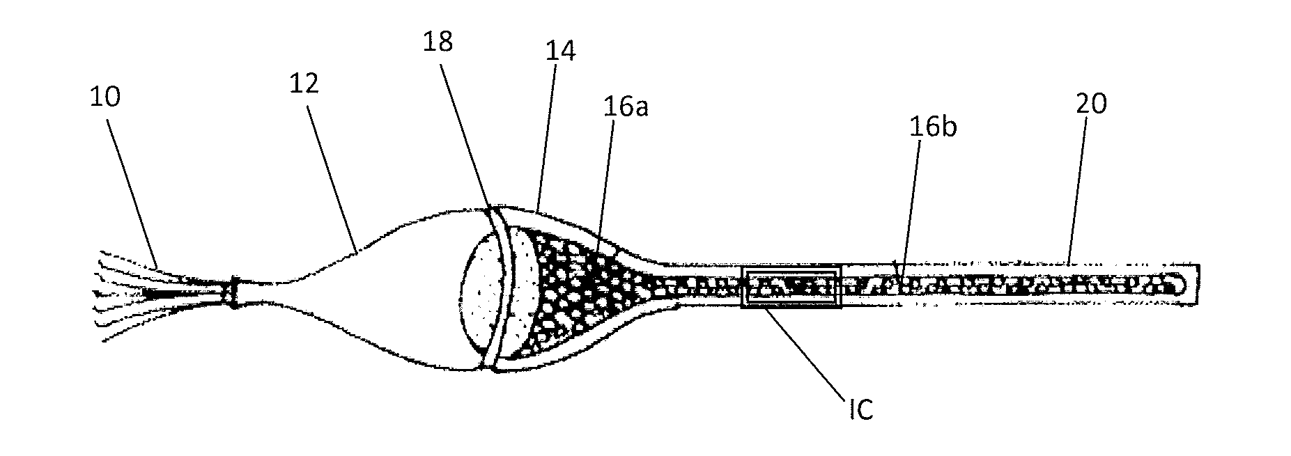
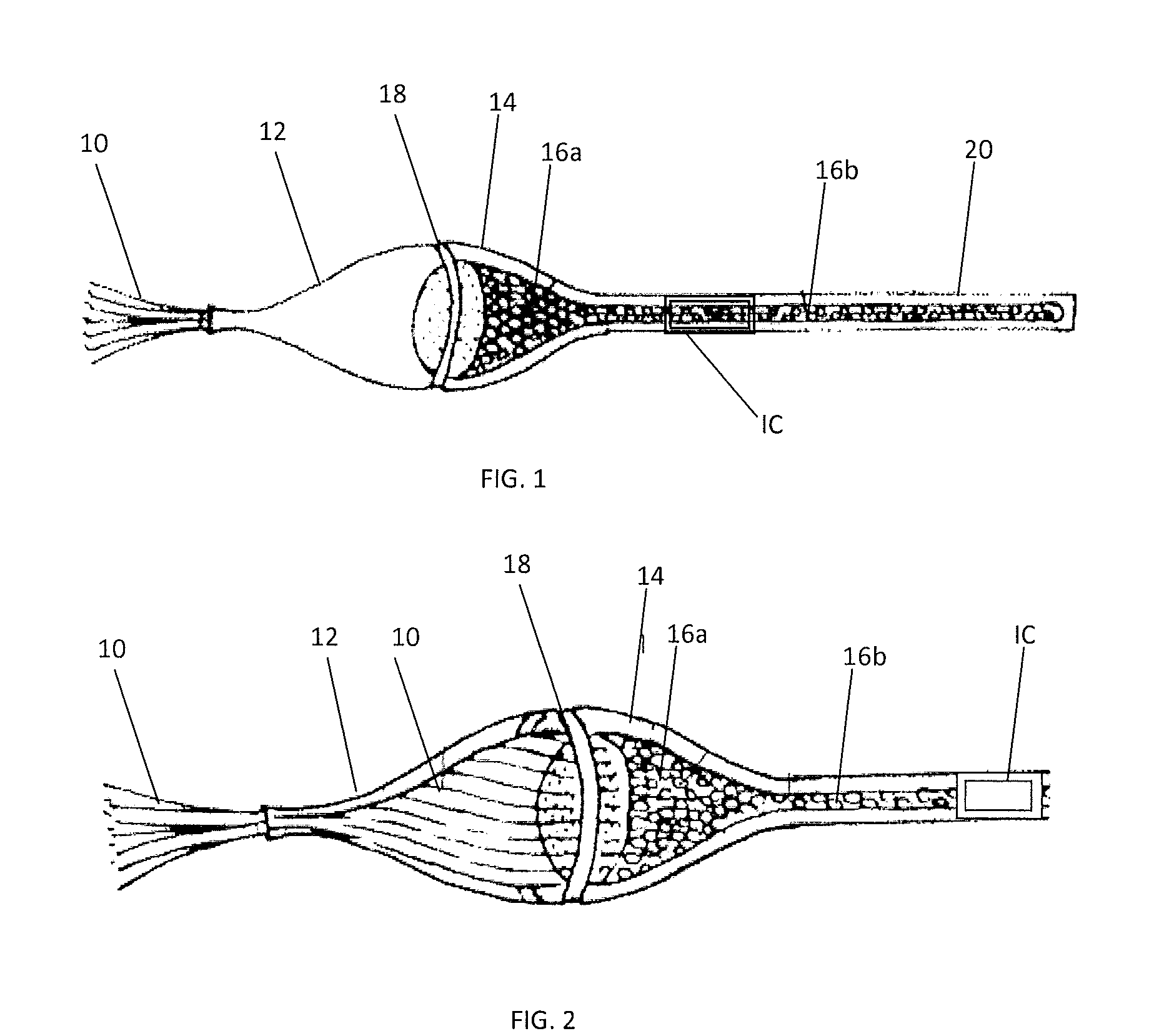
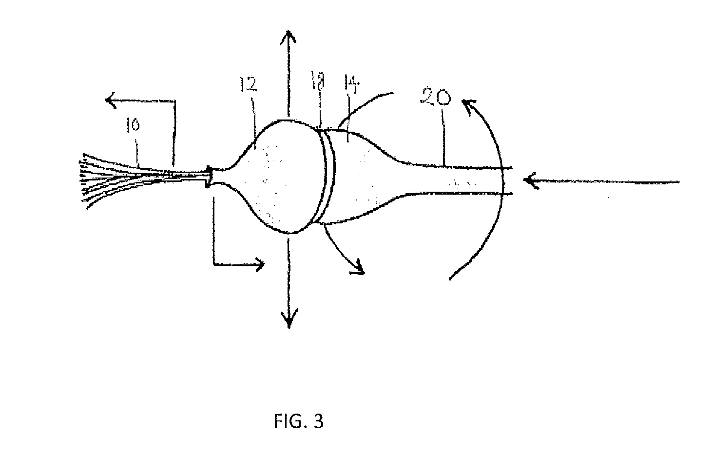
[0041]FIG. 1 shows a perspective view of the present invention. The microcilios 10 are “hairlike” micro suction fingers or filaments made from soft ultra absorbent material. Their primary function is to absorb liquid accumulation in the auditory canal, to alleviate discomfort and infection potential. The microcilios 10 (also referred to herein as absorbent filaments) protrude from an opening in an oval capsule composed of a pivot capsule 12 and a cilia capsule 14. Specifically, the microcilios 10 protrude from a small opening located at the extreme end of the pivot capsule 12. The pivot capsule 12 and cilia capsule 14 are held together by a rotary channel 18 that allows for both rotational and pivotal functions. The cilia capsule 14 connects at its lower end with the extension element rod 20 of the present invention that serves as a handle that enables projection of the microcilios 10 by rotational manipulation. Inside the cilia capsule 14 and the extension element the device is filled with a reservoir sponge 16 whose main function is to provide liquid retention capacity and storage for the liquid captured by the microcilios 10. The reservoir sponge or spongy body, comprised of an absorbent head 16a and an absorbent body 16b, serves as a storage medium for the liquid until it is disposed of A tiny window or liquid indicator IC, is located nearby the cilia capsule (inside the gyratory mechanism) and it is intended to indicate when the liquid has been absorbed.
[0042]FIG. 2 depicts a closer perspective view that shows in detail the cilia capsule embodiment of the invention. In this illustration it can be better observed the relationship and connectivity between the microcilios 10 and the reservoir sponge absorbent head 16a. These two elements, microcilios 10 and reservoir sponge absorbent head 16a, interconnect at a point just below the rotary channel 18. The location of the reservoir sponge absorbent head 16a and the rotary channel 18 allows for easy manipulation of the projection of the microcilios by twisting and maneuvering the extension 20. The delicate complexion of the microcilios 10 allows for liquid or water absorption deep into the auditory canal without risk of perforation or laceration to the eardrum. The design of the upper extreme of the pivot capsule 12, from where the microcilios 10 protrude, keeps the solid elements of the present invention from entering the auditory canal.
[0043]FIG. 3 is a perspective view, which illustrates the movement and functionality of some of the embodiments of the present invention. This figure shows that through the twisting and manipulation of the extension 20 the rotary channel 18 contained in the capsule enables control of the projection of the microcilios 10. The upward or downward movement of the extension 20 allows pivotal control of the microcilios 10 for better and more complete access to accumulated liquid in the auditory canal. The manner in which the microcilios 10 open in a “fanlike” fashion enables the present invention to maximize the performance of the liquid or water absorption.

PUM

no PUM

Description & Claims & Application Information

We can also present the details of the Description, Claims and Application information to help users get a comprehensive understanding of the technical details of the patent, such as background art, summary of invention, brief description of drawings, description of embodiments, and other original content. On the other hand, users can also determine the specific scope of protection of the technology through the list of claims; as well as understand the changes in the life cycle of the technology with the presentation of the patent timeline. Login to view more.
Why Eureka
Try Eureka