Conveyors for box making machines

Active Publication Date: 2015-09-17
SUN AUTOMATION
View PDF8 Cites 13 Cited by
  • Summary
  • Abstract
  • Description
  • Claims
  • Application Information

AI Technical Summary

Problems solved by technology

However when a digital printer is used instead of the above system, a problem may arise when the boards are conveyed to the printer by a vacuum belt conveyor.
If any of the belt apertures adjacent to the edges of the boards is not covered or closed by the board, ink emitted from these apertures is subject to deviation (“windage”) from its intended position on the image being printed on the board.
If the vacuum used to hold the boards on the conveyor belt is free to divert the flow of ink from the print head to the board to form the desired image, the res

Method used


Image

  • Conveyors for box making machines
  • Conveyors for box making machines
  • Conveyors for box making machines

Examples


Embodiment Construction

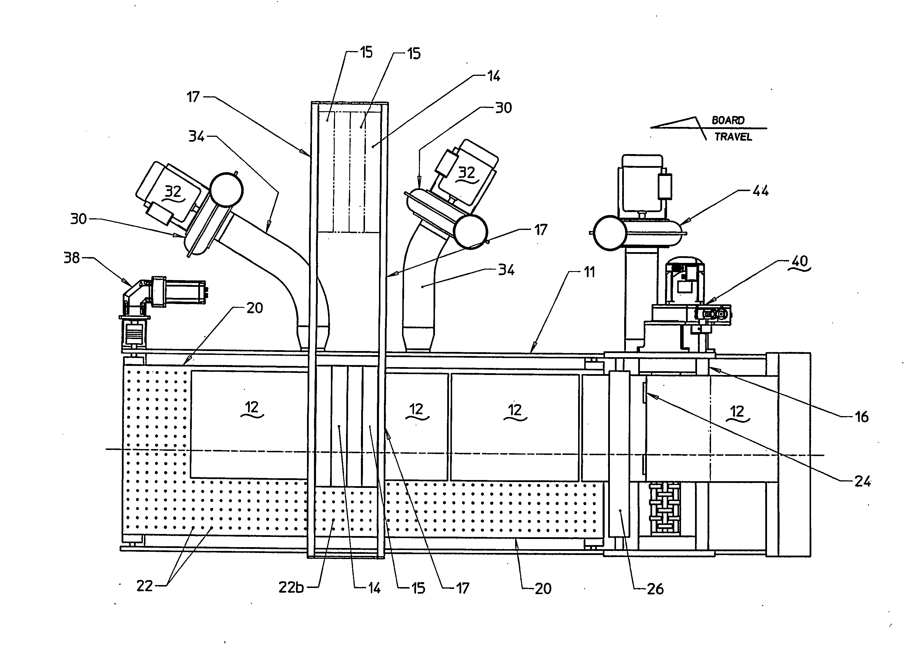
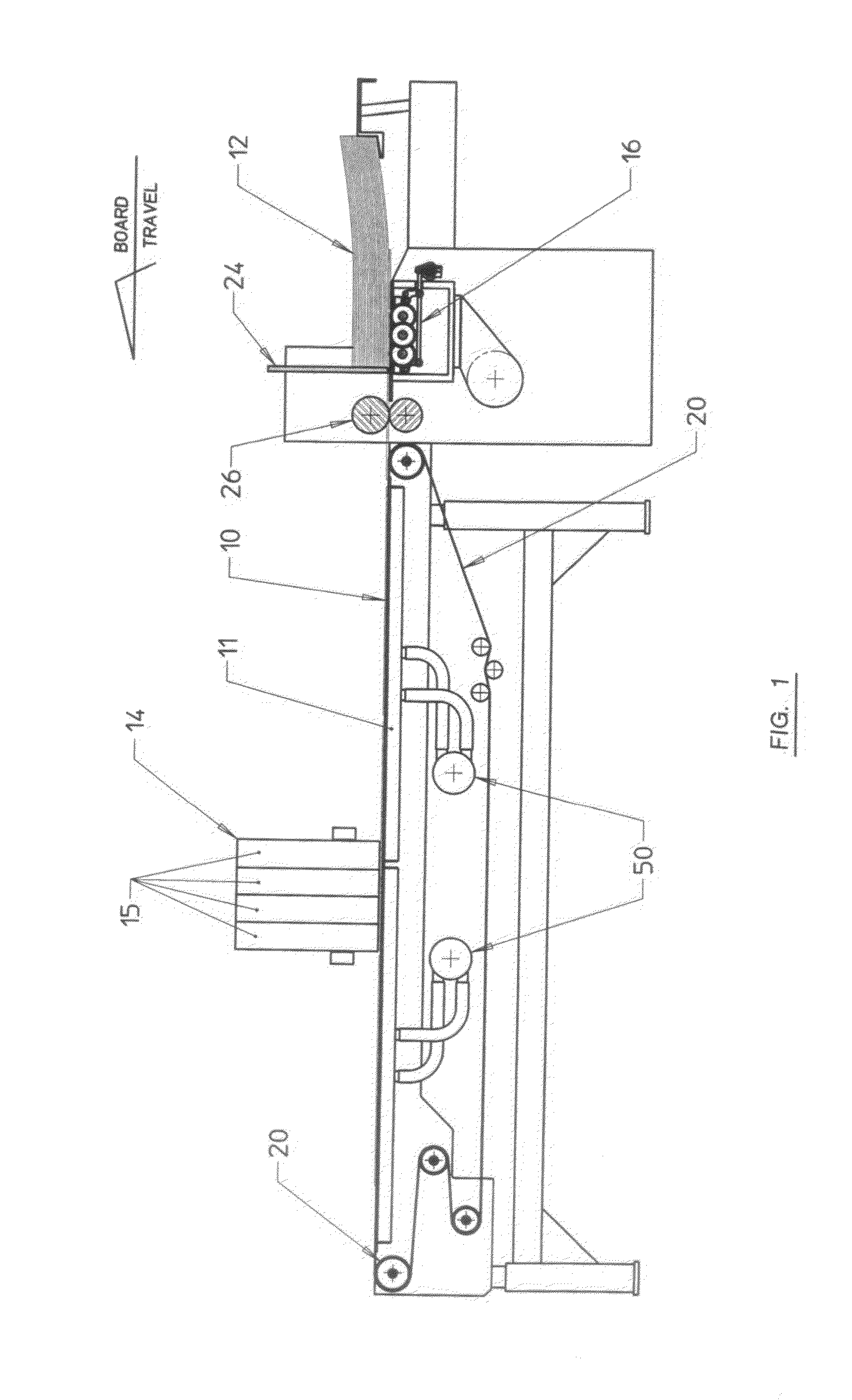
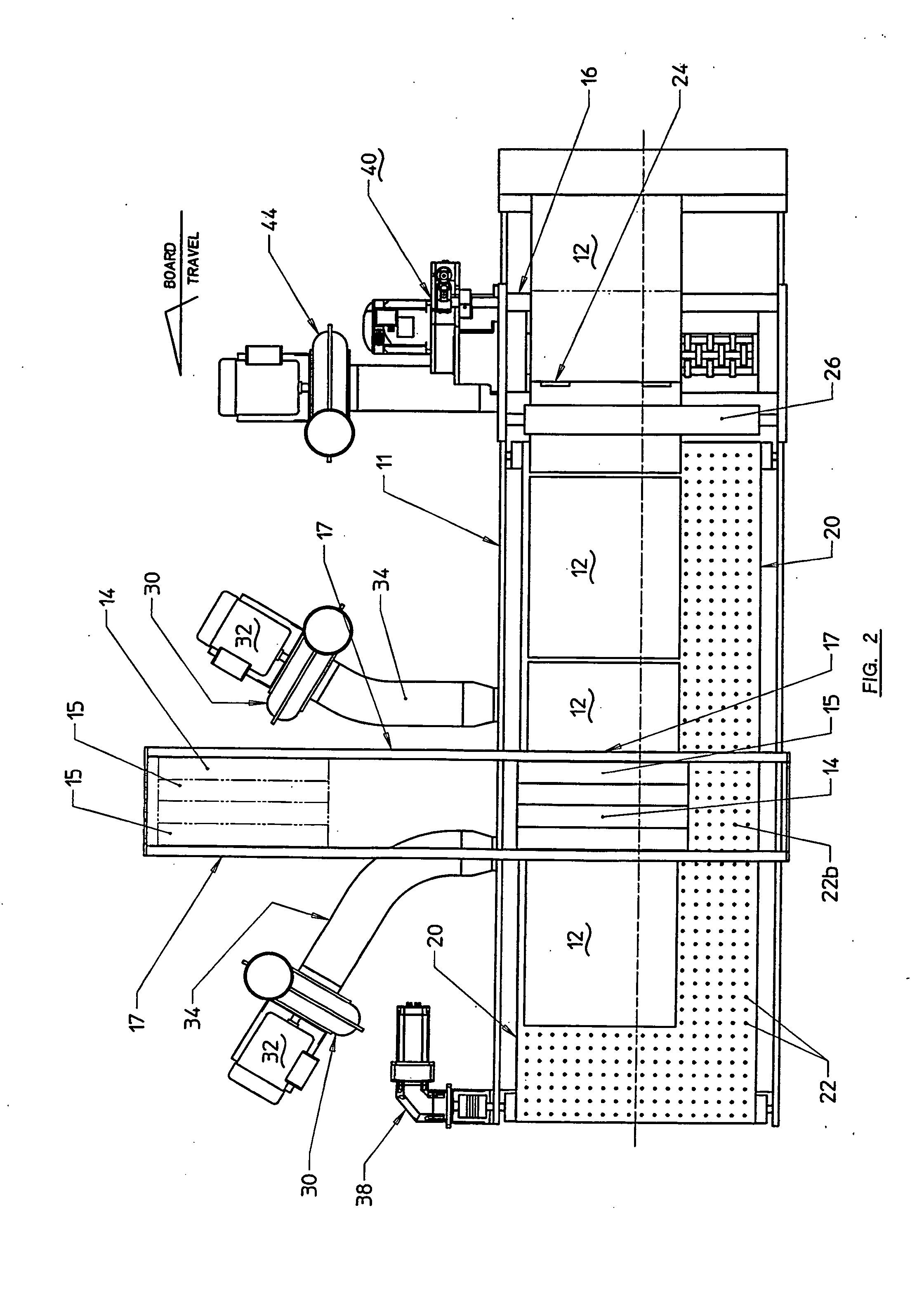
[0026]Referring to the drawings in detail and initially to FIGS. 1-5, there is shown for illustrative purposes only, one preferred embodiment of the present invention including a belt conveyor 10 for sequentially feeding sheets such as corrugated boards 12 one behind the other in horizontal planes along a horizontal path to a digital printer 14 for printing an image on the top surface of the boards 12 when they arrive below the printer 14. Also shown is a feeder 16 for feeding the boards 12 one by one in a predetermined timed fashion to conveyor 10 from a stack of boards. Feeder 16 is a timed feeder such as described in U.S. Pat. No. 7,635,124 B2 to Sardella whose disclosure is hereby incorporated by reference into the present application as part hereof. For a particular job, feeder 16 delivers a board 12 to conveyor 10 at a predetermined interval of time so that the boards 12 are transported to the printer 14 with the same predetermined space or gap 18 between successive boards, on...


PUM

PropertyMeasurementUnit
Timeaaaaaaaaaa
Flow rateaaaaaaaaaa
Sizeaaaaaaaaaa

Abstract

A vacuum belt conveyor sequentially delivers sheet articles to a digital printer. The sheets are held in position by vacuum on the underside of the sheets through apertures in the belts and covered by the sheets. A plurality of independent plenums on the underside of the belt have chambers respectively communicating with rows of apertures extending along the belt. Vacuum is selectively applied from a manifold only to the plenum chambers that supply apertures that are covered by the sheets so that the ink from the printer will not be directed from its intended position on the sheet by vacuum from adjacent uncovered belt apertures. The sheets are fed to the conveyor in synchronism with the conveyor speed by a timed feeder so that the sheets are carried by the conveyor with a predetermined gap between the sheets and no belt apertures in the gap. A sensor counts the apertures in the belt and activates the feeder at predetermined time intervals.

Description

FIELD OF THE PRESENT INVENTION[0001]The present invention generally relates to conveyors and methods of conveying articles such as sheets, and more particularly in a preferred form, to conveyors for box making machines where the articles are typically corrugated cardboard sheets called “boards” or “corrugated boards” or even “corrugated” alone.BACKGROUND OF THE INVENTION[0002]In the field of box-making, sheets, typically corrugated boards, are sequentially conveyed along a horizontal path to one or more stations along the path where operations like cleaning, printing, cutting, slotting or scoring are performed on the boards in a timed sequence. It is essential that the boards arrive at each of the aforementioned work stations in “registration”, that is, in a predetermined timed sequence. Various examples of corrugated board conveyors including timed feeders may be found in U.S. Pat. Nos. 4,045,015; 4,494,745; 4,632,378; 4,681,311; 4,889,331; 5,184,811 and, 7,635,124 B2.[0003]Several...

Claims


Application Information

Patent Timeline
IPC IPC(8): B65G15/58B41F17/24B31B1/88B31B50/88
CPCB65G15/58B31B1/88B31B2201/88B31B2201/0247B41F17/24B65H7/02B65H11/005B65H2406/362B65H2406/42B65H2511/10B65H2511/514B65H2701/1764B41J11/0085B65H2511/22B65H2513/10B31B50/88B31B2100/00B31B50/07B31B50/042B31B2110/35B41J11/007B65H2511/30B65H2513/512B65H2220/01B65H2220/11B65H2220/02B65H5/224
Inventor HERSHFELD, ROBERT MICHAEL
Owner SUN AUTOMATION
Why Eureka
Try Eureka