Head mountable device

a technology of mounting device and head, which is applied in the direction of mechanical pattern conversion, instrument, cathode-ray tube indicator, etc., can solve the problems of inconvenient installation, cumbersome and/or costly, and achieve the effect of improving the quality of outpu

Active Publication Date: 2015-09-17
SONY COMPUTER ENTERTAINMENT INC
View PDF4 Cites 30 Cited by
  • Summary
  • Abstract
  • Description
  • Claims
  • Application Information

AI Technical Summary

Benefits of technology

[0022]This aspect of the present invention uses a similar principle to that of the first aspect, although in this case, it is a reflected image of an eye of the user wearing the head-mounted device which is visible to a camera of the mobile device held on the frame. This allows a mobile device comprising an eye-tracking facility to track the eye of the user using the reflected image. Various operations can then be performed by the mobile device based on the tracked eye movements. Advantageously, when wearing the head-mounted device of the present invention, the user does not have to hold anything in their hands or act differently from the way in which they would naturally act.

Problems solved by technology

Other HMDs, however, allow the user only to see the displayed images, which is to say that they obscure the real world environment surrounding the user.
The present invention recognises that a problem facing the

Method used


Image

  • Head mountable device
  • Head mountable device
  • Head mountable device

Examples


Embodiment Construction

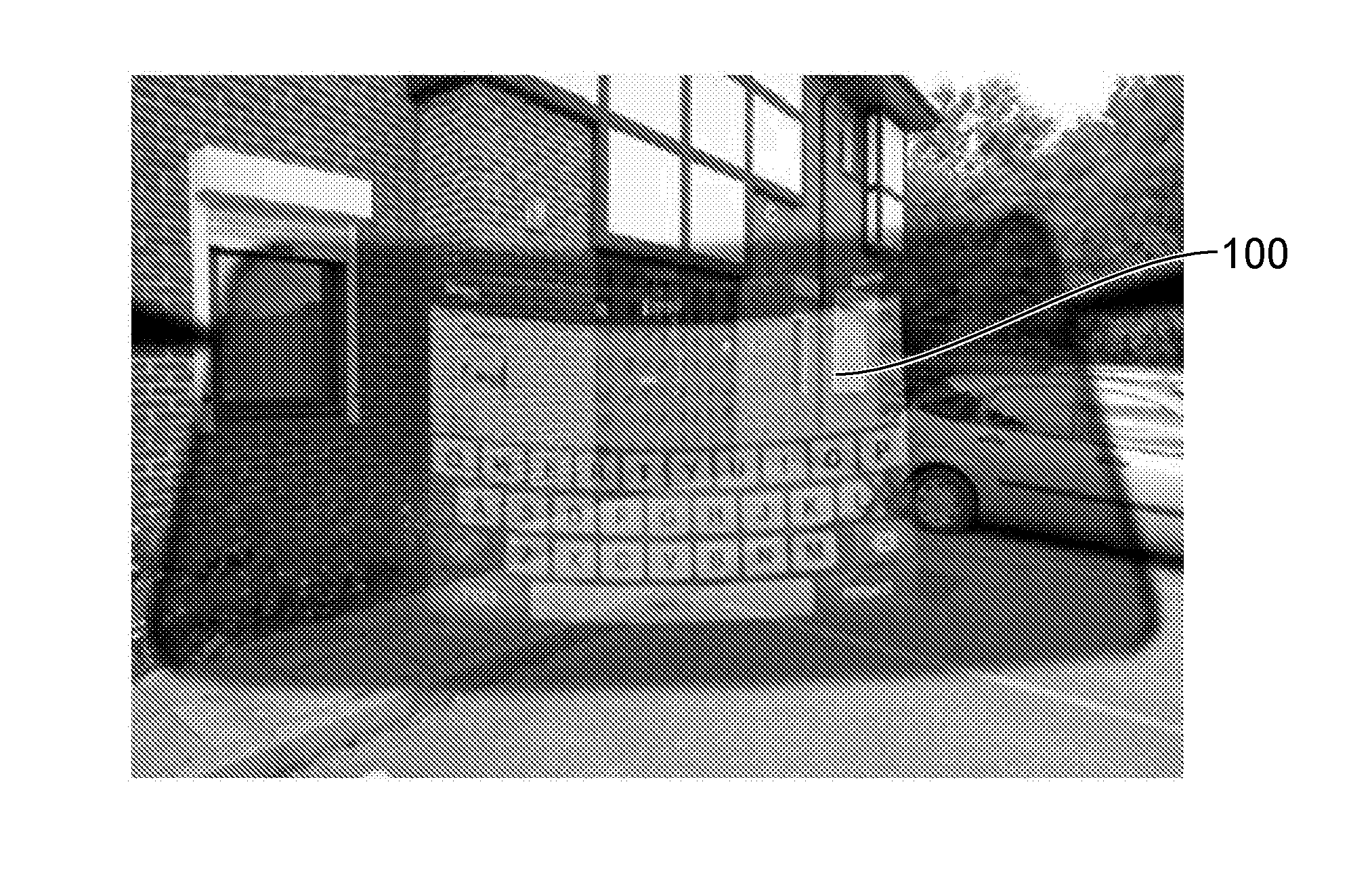
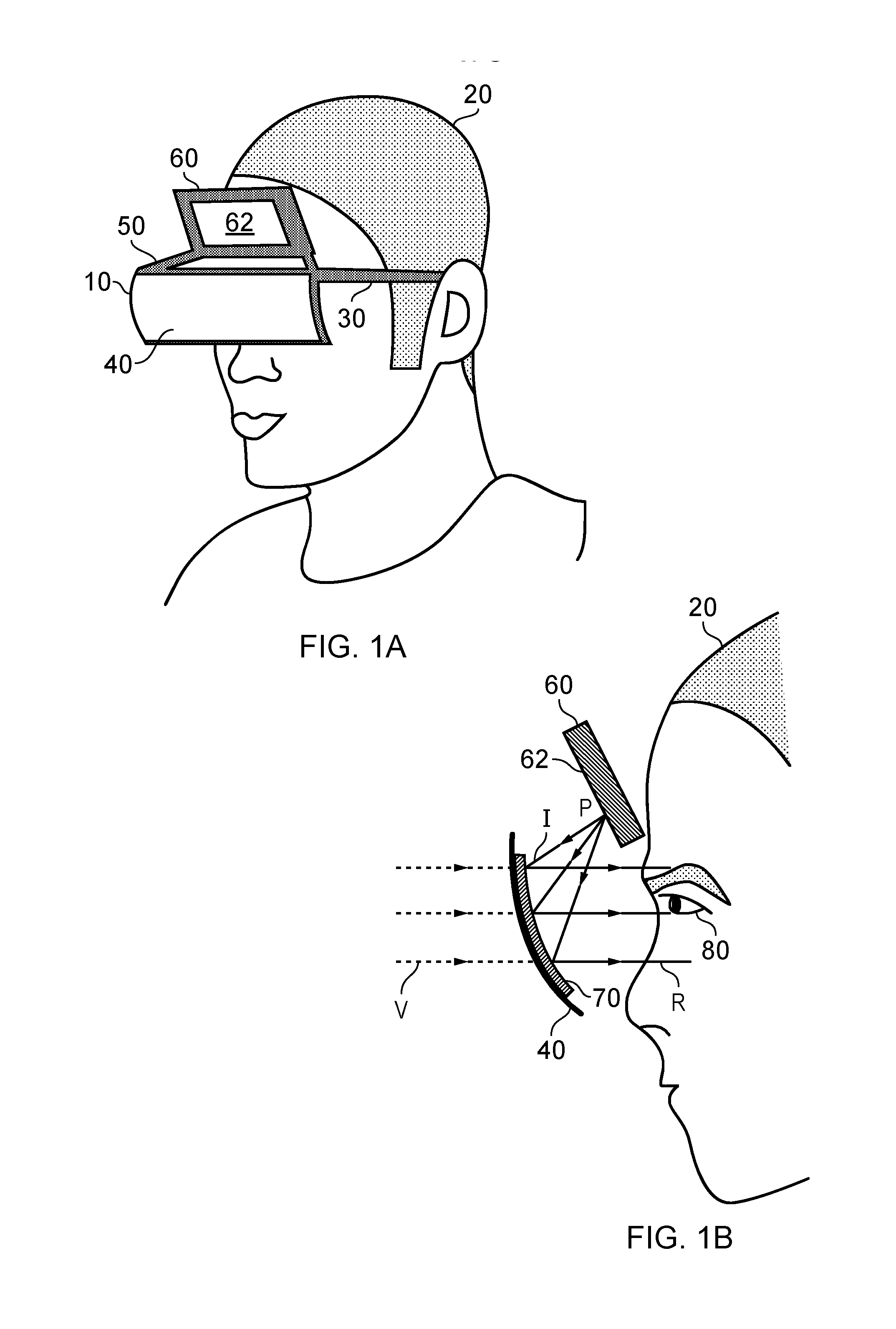
[0030]Referring now to the drawings, FIG. 1A shows a head-mountable display device (HMD) 10 according to an embodiment of the present invention. In order to clearly demonstrate the way in which the HMD 10 operates, it is illustrated in a situation in which it is mounted on the head of a user 20.

[0031]The HMD 10 comprises a frame 30 which allows the HMD to be mounted on the head of the user. In this particular example, the frame 30 is similar to the frames used in ordinary spectacles. There are, however, many different variations that could be used. The frame could, for example, be comprised within a hat or helmet which is worn by the user. Accordingly, the frame 30 provides a frame to be mounted onto a user's head, the frame defining an eye display position which, in use, is positioned in front of an eye of the user. In embodiments, the eye display position is occupied by a reflective element, to be described below.

[0032]The frame 30 defines an eye display position which is position...


PUM


Abstract

A head-mountable display device includes a head-mountable frame defining an eye display position which, in use, is positioned in front of an eye of the user. The device also includes a reflective element mounted with respect to the eye display position and comprising a reflective surface which, in use, is visible to the user's eye. The device further includes a mobile device holder configured to hold a mobile device at a location and orientation on the frame. The reflective surface is configured to reflect light incident thereupon to form a reflected image. The location and orientation in which the mobile device is held relative to a location and orientation of the reflective surface are such that light arriving from the mobile device screen held in the holder is reflected by the surface so that a reflected image of at least a portion of the screen is visible to the user.

Description

BACKGROUND[0001]1. Field of the Invention[0002]This invention relates to head-mountable devices.[0003]2. Description of the Related Art[0004]The “background” description provided herein is for the purpose of generally presenting the context of the disclosure. Work of the presently named inventors, to the extent it is described in this background section, as well as aspects of the description which may not otherwise qualify as prior art at the time of filing, are neither expressly or impliedly admitted as prior art against the present invention.[0005]A head-mountable display (HMD) is an image or video display device which may be worn on the head or as part of a helmet or other head mounted frame. Either one eye or both eyes are provided with small electronic display devices.[0006]Some HMDs allow a displayed image to be superimposed on a real-world view. This type of HMD can be referred to as an optical see-through HMD and generally requires the display devices to be positioned somewh...

Claims


Application Information

Patent Timeline
IPC IPC(8): G02B27/01G06F3/01
CPCG02B27/0172G02B2027/011G06F3/013G02B27/017G02B27/0093G02B27/0176G02B2027/0138G02B2027/0154G02B2027/0187G06F3/012
Inventor BICKERSTAFF, IAN HENRYBENSON, SIMON MARK
Owner SONY COMPUTER ENTERTAINMENT INC
Why Eureka
Try Eureka