Antenna orientation adjustment assistance device and antenna device installation method

an assistance device and antenna technology, applied in waveguide type devices, measurement devices, instruments, etc., can solve the problems of time-consuming antenna installation, inability to adjust the orientation of difficulty in practice to set the antenna toward the direction, etc., to achieve quick and accurate installation of the antenna device

Inactive Publication Date: 2015-09-17
NEC CORP
View PDF2 Cites 18 Cited by
  • Summary
  • Abstract
  • Description
  • Claims
  • Application Information

AI Technical Summary

Benefits of technology

[0019]According to the exemplary aspects of the present invention, any worker can quickly and accurately install an antenna device.

Problems solved by technology

However, because two orientations, the elevation and the azimuth, need to be set to adjust the antenna orientation, it is extremely difficult in practice to set the antenna orientation toward the direction in which the maximum reception level can be achieved.
It is time-consuming work to set the antenna toward the direction with the maximum reception level in a step-by-step manner by making fine adjustment of the elevation and the azimuth by checking the reception level each time.

Method used


Image

  • Antenna orientation adjustment assistance device and antenna device installation method
  • Antenna orientation adjustment assistance device and antenna device installation method
  • Antenna orientation adjustment assistance device and antenna device installation method

Examples


first exemplary embodiment

[0039]A first exemplary embodiment of the invention is described hereinafter.

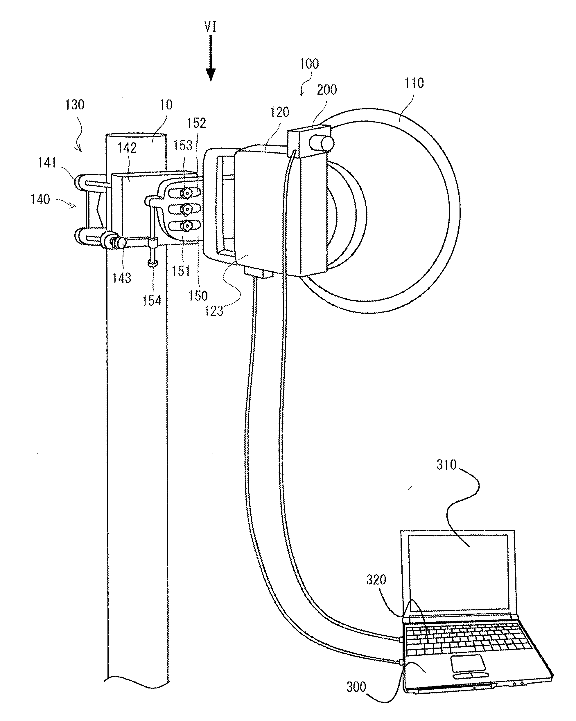
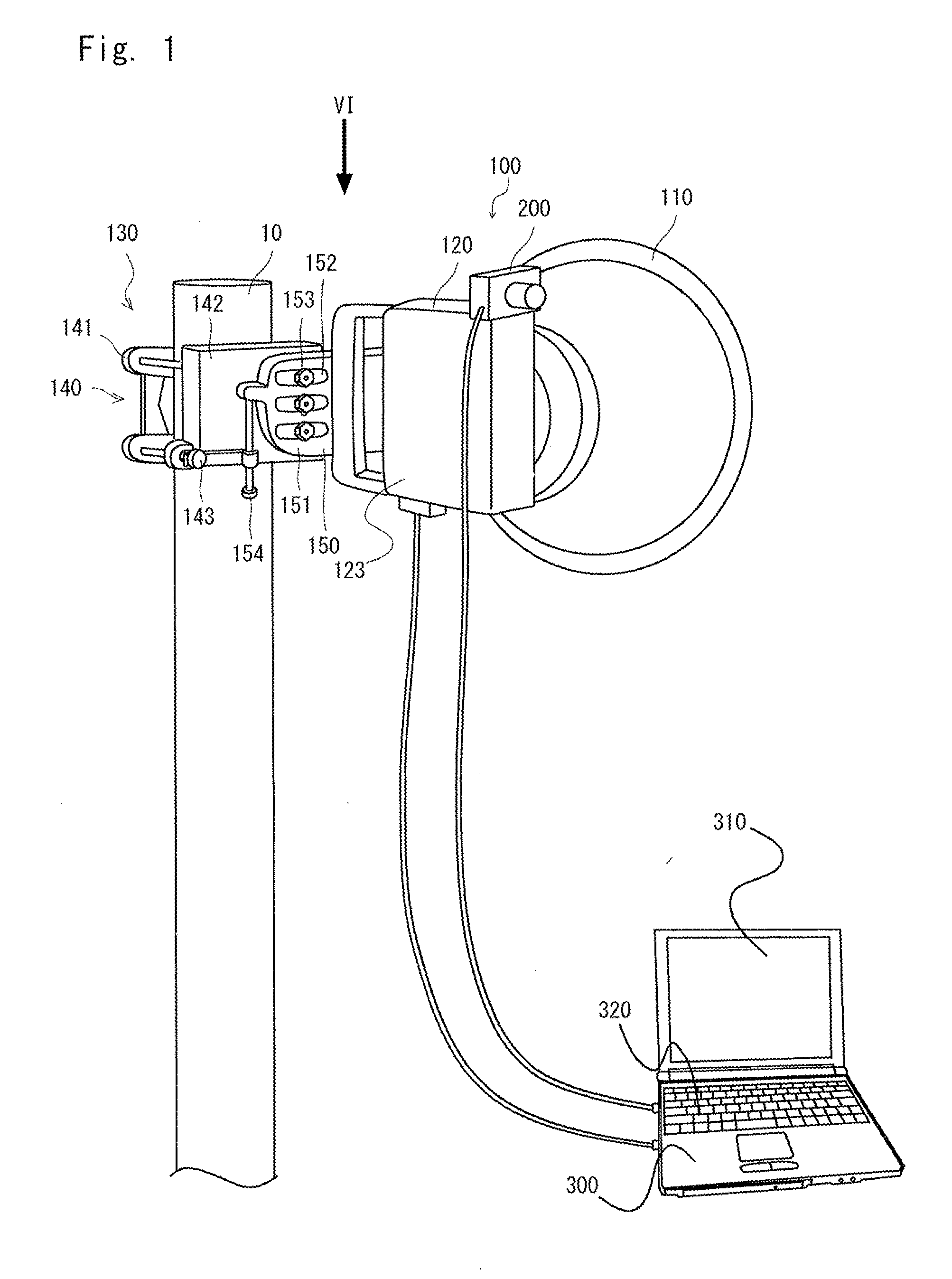
[0040]FIG. 1 is a view showing the installation work of an antenna device 100 according to this exemplary embodiment. A known antenna device can be used. Although a so-called parabolic antenna is shown as an example, the type of the antenna is not particularly limited in the application of this exemplary embodiment.

[0041]The structure of an antenna device 100, though it is already known, is briefly described hereinafter.

[0042]FIG. 1 shows the antenna device 100 mounted on a mast 10 and viewed from the back.

[0043]The antenna device 100 includes an antenna unit 110, a transmitting and receiving unit 120, and a mounting means 130.

[0044]The transmitting and receiving unit 120 is an electrical circuit unit that includes a receiving circuit 121 and a transmitting circuit 122 (see FIG. 3) and performs modulation and demodulation of signals according to the need.

[0045]The transmitting and receiving unit 120 include...


PUM

PropertyMeasurementUnit
angleaaaaaaaaaa
angleaaaaaaaaaa
angleaaaaaaaaaa

Abstract

An antenna orientation adjustment assistance device that allows any worker to quickly and accurately install an antenna device is provided. An antenna device (100) is temporarily installed. Further, a camera (200) is mounted on the antenna device (100). Then, the antenna orientation adjustment assistance device includes a reception strength detection unit (420) that detects a reception strength of radio waves received by an antenna unit (110), a position calculation unit (414) that calculates a relative angle position of the antenna unit (110) by using an image taken by a camera (200) fixed relative to the antenna unit (110), and a reception strength recording unit (430) that records the relative angle position of the antenna unit (110) and the reception strength at the relative angle position in association with each other.

Description

TECHNICAL FIELD[0001]The present invention relates to a device that assists in adjusting the orientation of an antenna.BACKGROUND ART[0002]When installing a directional antenna, it is important to place it toward an appropriate direction in order to maximize the reception level. Currently, when adjusting the antenna orientation, a worker seeks the orientation with the maximum reception level by a process of trial and error by changing the antenna orientation in a step-by-step manner and installs the antenna in that orientation.[0003]However, because two orientations, the elevation and the azimuth, need to be set to adjust the antenna orientation, it is extremely difficult in practice to set the antenna orientation toward the direction in which the maximum reception level can be achieved. It is time-consuming work to set the antenna toward the direction with the maximum reception level in a step-by-step manner by making fine adjustment of the elevation and the azimuth by checking the...

Claims


Application Information

Patent Timeline
Patent Type & Authority Applications(United States)
IPC IPC(8): H01Q1/12H01Q3/02
CPCH01Q3/02H01Q1/1257H01Q1/1228Y10T29/49016
Inventor HIRABE, MASASHI
Owner NEC CORP
Why Eureka
Try Eureka