Electrical connector firmly assembled on and conveniently detachable from a panel via an extraction tool

Active Publication Date: 2015-09-17
FOXCONN INTERCONNECT TECHNOLOGY LIMITED
View PDF6 Cites 2 Cited by
  • Summary
  • Abstract
  • Description
  • Claims
  • Application Information

AI Technical Summary

Benefits of technology

The present invention is aimed at providing an electrical connector that is securely attached to a panel but can also be easily detached from it using a special tool.

Problems solved by technology

The utility does not disclose a method how the electrical connector is assembled on the printed circuit board.

Method used


Image

  • Electrical connector firmly assembled on and conveniently detachable from a panel via an extraction tool
  • Electrical connector firmly assembled on and conveniently detachable from a panel via an extraction tool
  • Electrical connector firmly assembled on and conveniently detachable from a panel via an extraction tool

Examples


Embodiment Construction

[0016]Reference will now be made in detail to the preferred embodiment of the present invention.

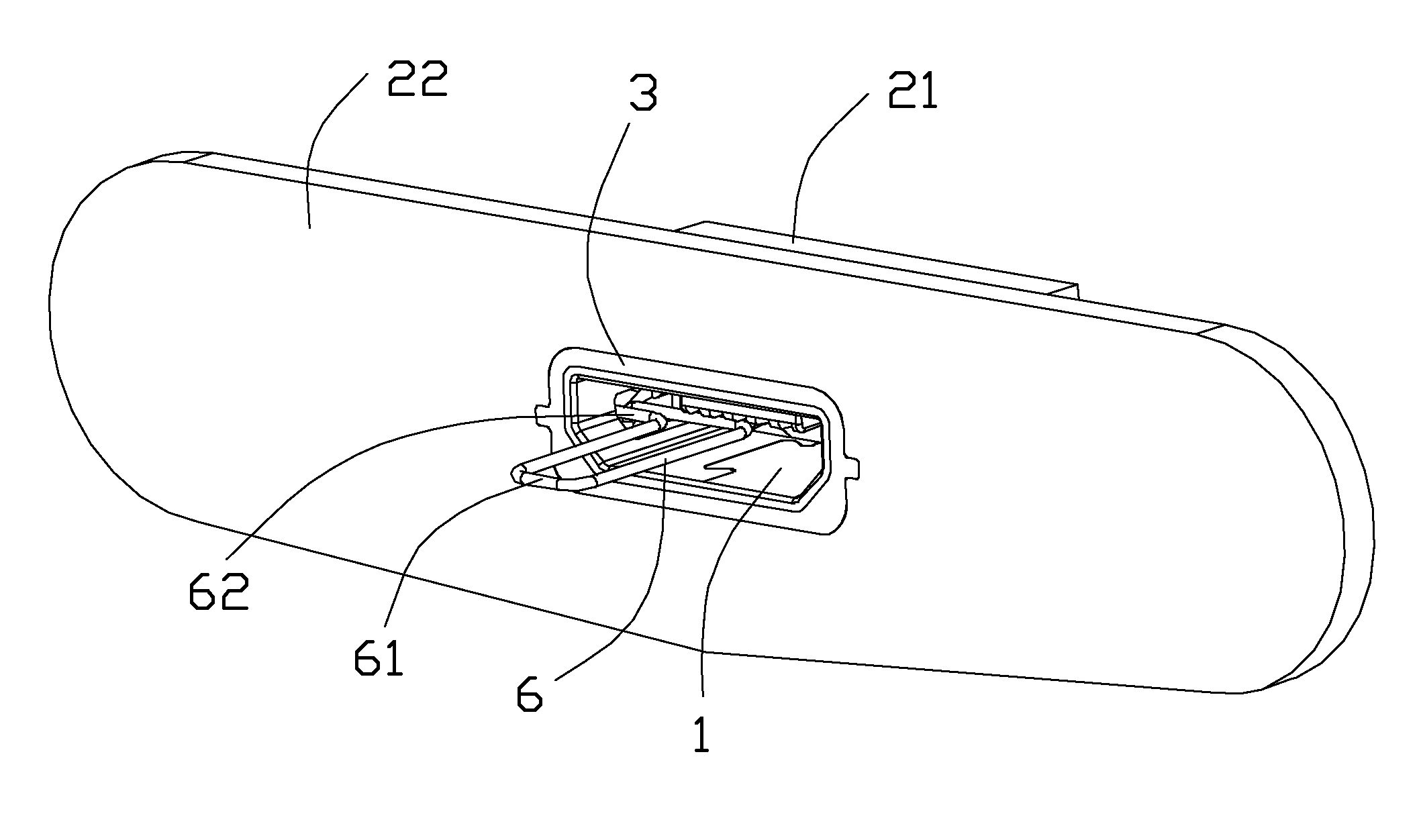
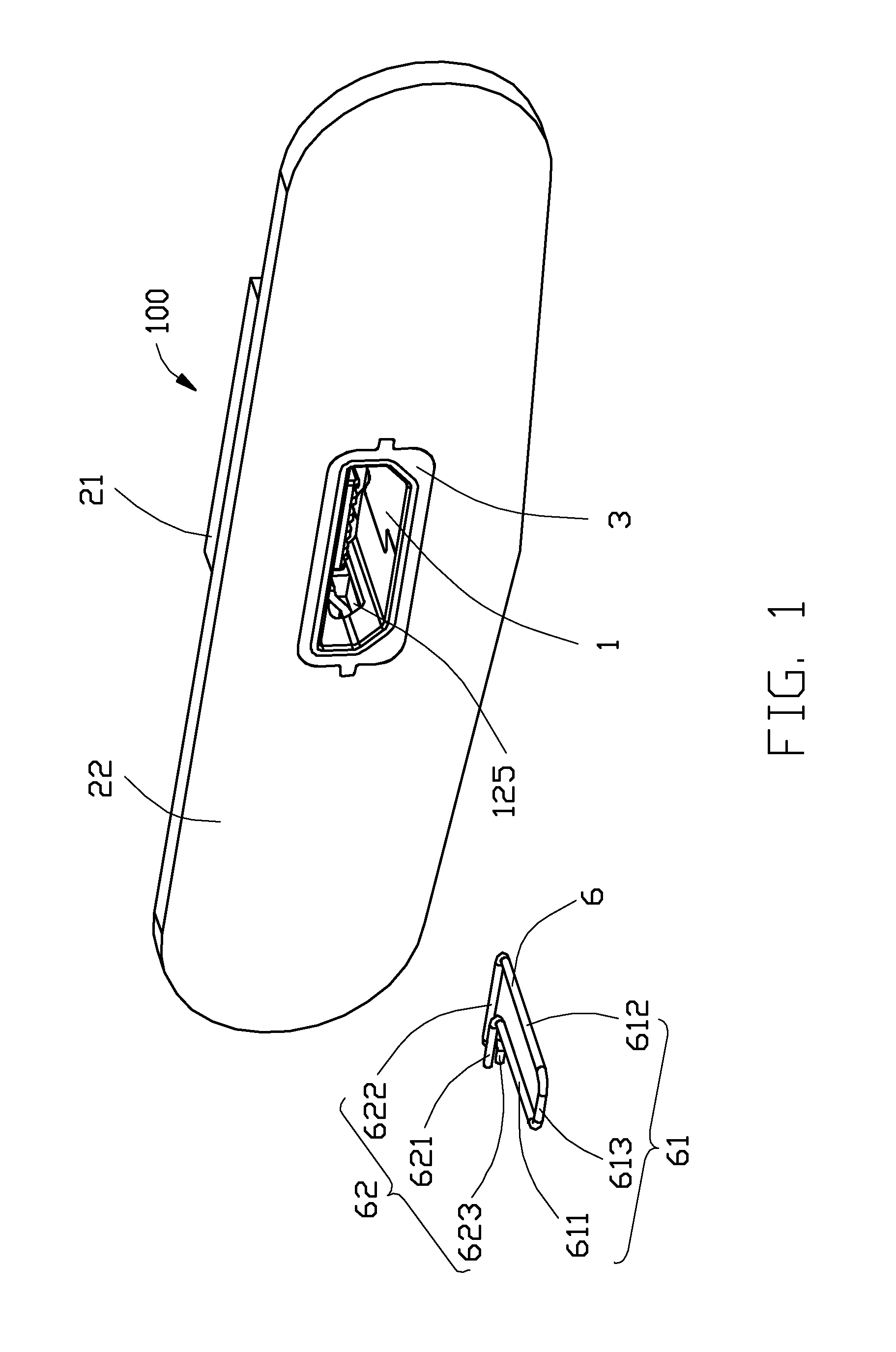
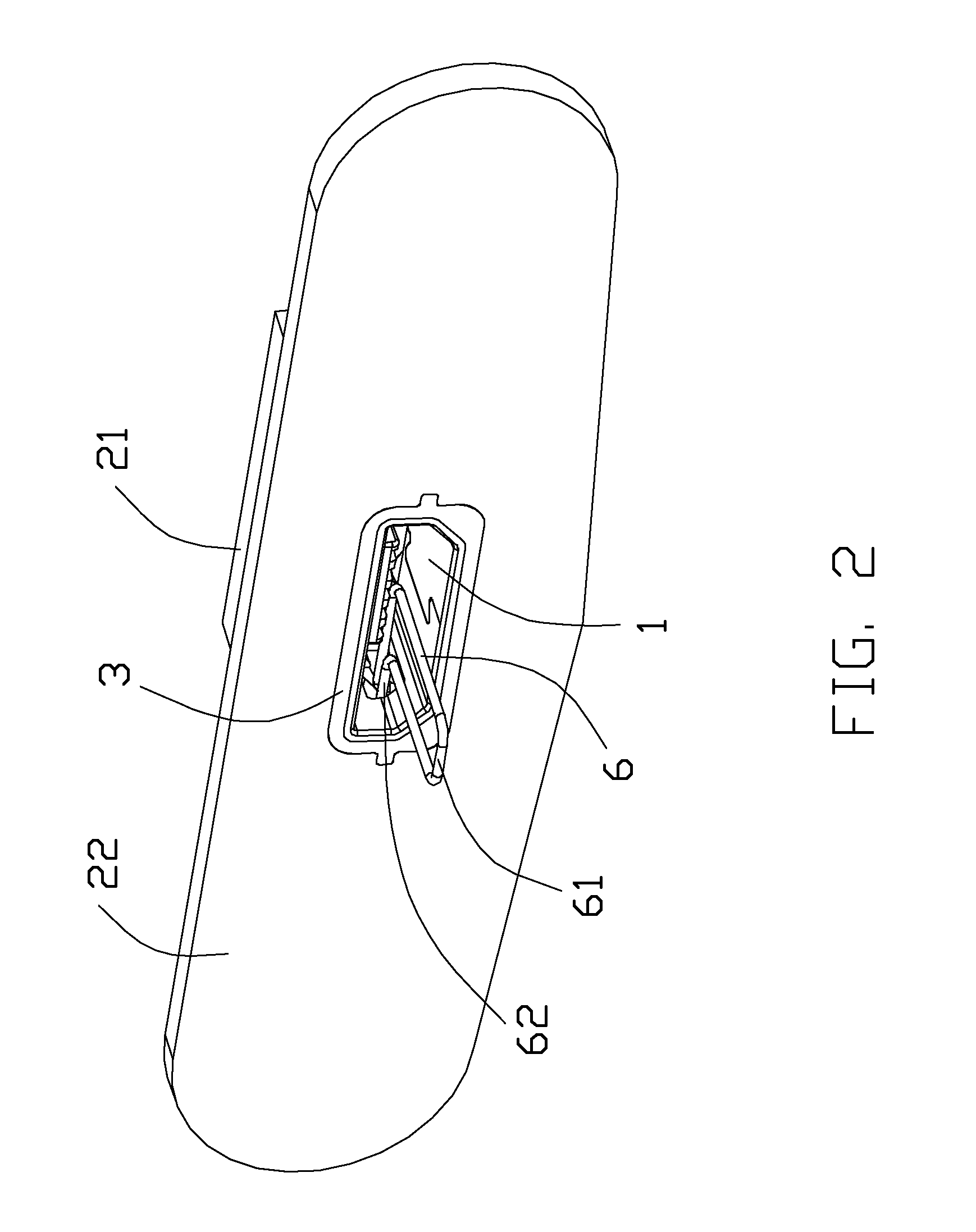
[0017]Referring to FIGS. 1-7, an electrical connector assembly 100 of the present invention, comprises an electrical connector 1, a panel 2 which the electrical connector 1 is assembled on, and a sealing ring 3 sandwiched between the electrical connector 1 and the panel 2 for waterproof An extraction tool 6 used for withdrawing the electrical connector 1 from the panel 2 is clearly shown in FIGS. 1-7, too. The electrical connector 1 is connected to a printed circuit board 5 via an adapter 4.

[0018]Referring to FIGS. 4, 5, 6, the electrical connector 1 comprises an insulative housing 10, a plurality of contacts 11 retained in the insulative housing 10, and a metal shell 12 covering the insulative housing 10 for defining a receiving space 124. The insulative housing 10 comprises a base portion 101, a first tongue portion 102 extending forwardly from the base portion 101, and a second tongue ...


PUM

PropertyMeasurementUnit
Flexibilityaaaaaaaaaa
Heightaaaaaaaaaa

Abstract

An electrical connector (100) includes an insulative housing (10), a number of contacts (11) retained in the insulative housing, and a metal shell (12) covering the insulative housing. Each contact includes a first contacting portion (111) for connecting with a mating plug connector and a second contacting portion (112) for connecting to a board-mounted adapter. The metal shell includes a top wall (121), a bottom wall (122), and a pair of sidewalls (123) connecting between the top wall and the bottom wall for cooperatively defining a receiving space (124). Each sidewall forms a flexible portion (120) for engaging a panel slot (2131). The flexible portion is stamped from the sidewall and the metal shell defines an aperture (125) for communicating with the panel slot. An extraction tool (6) is inserted into the receiving space to deform the flexible portion to detach away from the panel slot.

Description

BACKGROUND OF THE INVENTION[0001]1. Field of the Invention[0002]The present invention relates generally to an electrical connector, and more particularly to an electrical connector firmly assembled on a panel and conveniently detachable from the panel via an extraction tool.[0003]2. Description of Related Arts[0004]Taiwan Utility Model Pat. No. M385114 issued on Jul. 21, 2010 discloses an electrical connector assembled on a printed circuit board of a panel. The electrical connector comprises an insulative cover and a terminal module received in the insulative cover. The insulative cover has an upper wall, a lower wall, and a pair of sidewalls connecting with the upper wall and the lower wall for defining a receiving channel for the terminal module. The receiving channel has an insertion opening for a mating plug connector's insertion. The upper wall abuts against the printed circuit board. The terminal module comprises an insulative housing, a plurality of signal terminals and a gro...

Claims


Application Information

Patent Timeline
IPC IPC(8): H01R43/22H01R13/506
CPCH01R13/506H01R43/22H01R13/5202H01R13/743Y10T29/49208H01R13/633
Inventor GUO, JING-JIE
Owner FOXCONN INTERCONNECT TECHNOLOGY LIMITED
Why Eureka
Try Eureka