Shift control device for vehicle

Active Publication Date: 2015-09-24
MAZDA MOTOR CORP
View PDF6 Cites 6 Cited by
  • Summary
  • Abstract
  • Description
  • Claims
  • Application Information

AI Technical Summary

Benefits of technology

[0008]The present invention has been devised in view of the above-described matter, and an object of the present invention is to

Problems solved by technology

Therefore, there is a problem (i.e., an operation error) in that in a case in which the driver or another passenger touches the opera

Method used


Image

  • Shift control device for vehicle
  • Shift control device for vehicle
  • Shift control device for vehicle

Examples


Example

Embodiment 1

[0048][Entire Structure]

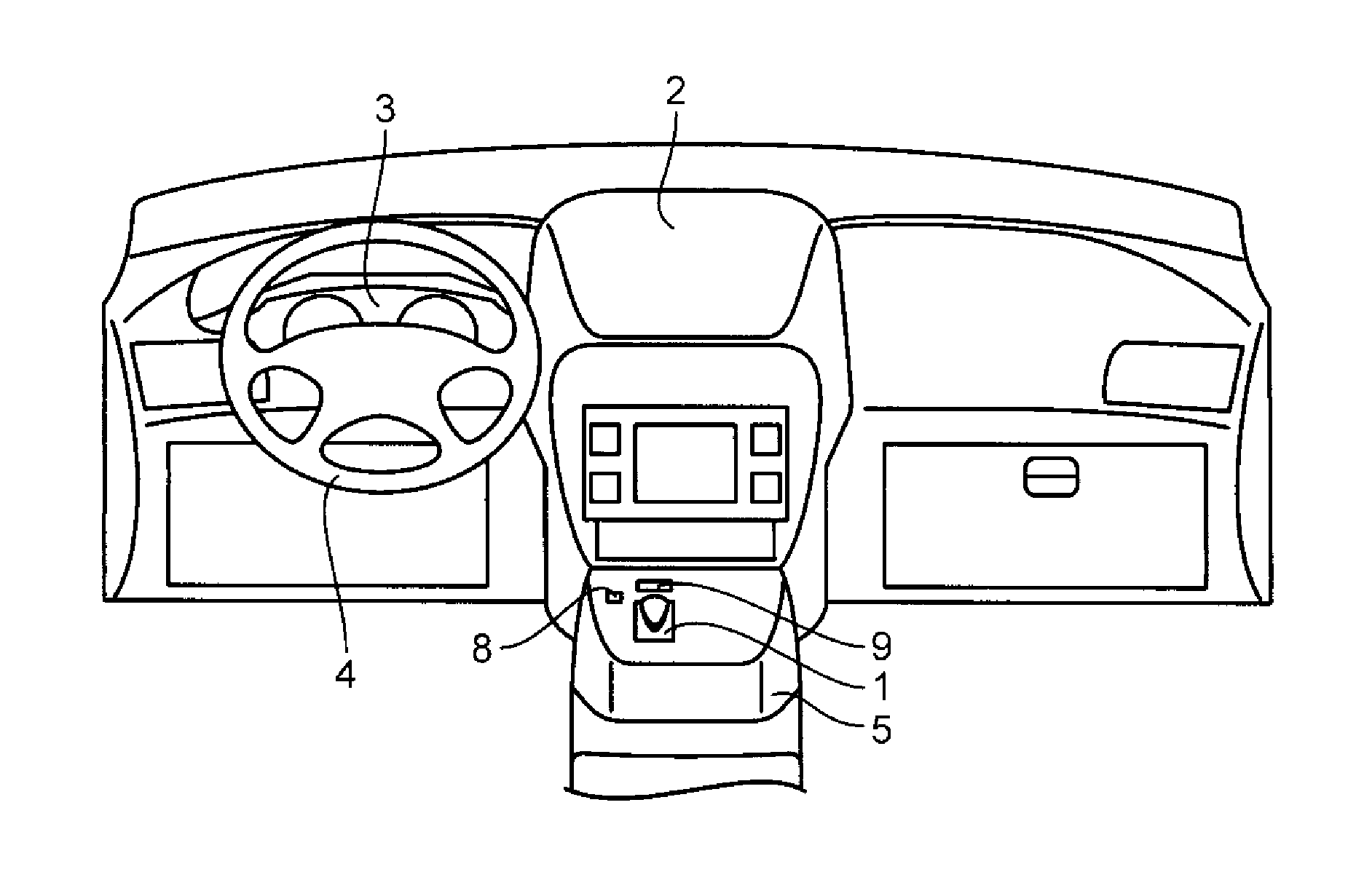
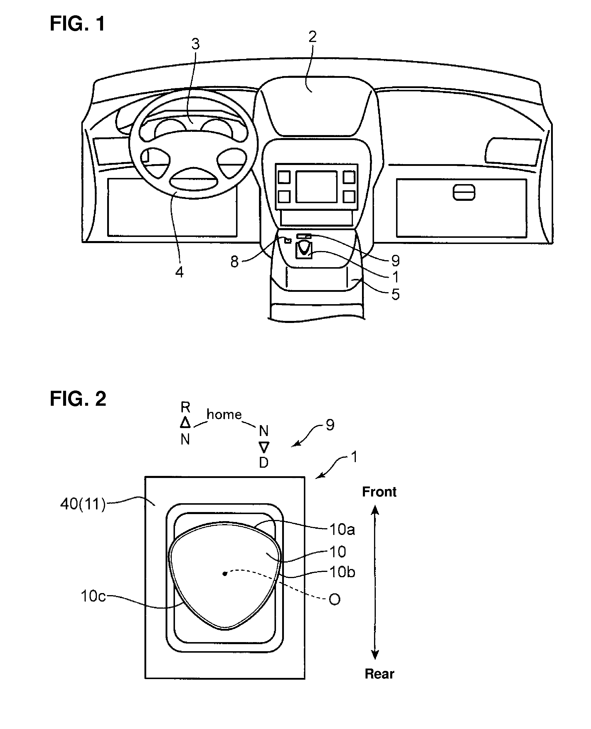
[0049]FIG. 1 is a diagram showing a structure of a vehicle-compartment front portion of a vehicle which is equipped with a shift device of a shift control device according to a first embodiment of the present invention. As shown in FIG. 1, a vehicle according to a first embodiment is a so-called left-handle vehicle in which a driver's seat and a steering wheel 4 are provided on a left side of the vehicle. An instrument panel 2 which extends in a vehicle width direction is provided at a vehicle-compartment front portion as shown in the figure. A meter unit 3 is provided on a driver's-seat side of the instrument panel 2, and behind the meter unit 3 is provided the steering wheel 4. A center console 5 is provided at a portion which extends rearward from a central portion, in the vehicle width direction, of the instrument panel 2, and on the center console 5 are provided a shift device 1, a parking switch 8, and an indicator 9 which constitute part of...

Example

[0050]In the first embodiment, the vehicle comprises an engine (not illustrated) which is comprised of an internal combustion engine, such as a gasoline engine or a diesel engine, and an automatic transmission 90 (FIG. 15) which transmits a drive force of the engine to wheels with speed reduction. The automatic transmission 90 is a multi-stage transmission (AT) which includes a planetary gear mechanism and automatically selects an appropriate one among plural speed-reduction ratios which are attained by the planetary gear mechanism according to a vehicle speed, an engine load, and the like. A shift range of the automatic transmission 90 includes a parking range in which a drive-force transmission is shut off, a forward-traveling range, i.e., a drive range, in which the drive force is transmitted so as to make the vehicle travel forward, and a backward-traveling range, i.e., a reverse range, in which the drive force is transmitted so as to make the vehicle travel backward.

[0051]The p...

Example

[0118]FIGS. 17, 18 and 19 show another embodiment (second embodiment) in which the dial 10 is arranged on the left side of the driver. As shown in FIG. 17, the vehicle according to the second embodiment is a so-called right-handle vehicle in which the driver's seat and the steering wheel 4 are provided on the right side of the vehicle. A shift device 201 which constitutes part of a shift control device for a vehicle according to the second embodiment is arranged on the center console 5 which is provided on the left side of the driver's seat, and this shift device 201 is operated by the driver with the left hand.

[0119]The shift device 201 of the second embodiment is different from the shift device 1 of the first embodiment only in the shape of a rotational-side guide face 224a of a rotational-side guide member 224. The other structures are the same. Hereinafter, only the shape of the rotational-side guide face 224a will be described.

[0120]In the second embodiment, as shown in FIG. 19...


PUM


Abstract

There are provided an operational member and a body portion supporting the operational member rotatably, clockwise or counterclockwise, from a home position and movably in a vehicle longitudinal direction from its rotated position. The body portion is configured to allow the rotated or moved operational member to return to the home position automatically. A shift range is changed to a neutral range when the operational member is rotated from the home position, and the shift range is changed to a traveling range (a drive range or a reverse range) when the operational member is moved in the vehicle longitudinal direction from the rotated position after the operational member is rotated from the home position. Herein, changing of the shift range to the drive range or the reverse range depends on the direction of the rotation of the dial from the home position.

Description

BACKGROUND OF THE INVENTION[0001]The present invention relates to a shift control device for a vehicle for changing a shift range of the vehicle.[0002]A so-called electric shifter device, in which a position of an operational member which corresponds to a shift lever is detected electrically for shifting, is known as a shift control device for a vehicle. This electric shifter device has been widely used in electric vehicles or hybrid vehicles which do not have a mechanical transmission. However, the electric shifter device which does not require a mechanical connection between the operational member and the transmission is superior in design flexibility, so that there is a tendency that vehicles provided with the mechanical transmission, such as conventional vehicles which install an engine (internal combustion engine) only as a power source, use the electric shifter device.[0003]In the electric shifter device having less limitation in the operational amount and the operational dire...

Claims


Application Information

Patent Timeline
IPC IPC(8): B60K20/02G05G5/05F16H59/08
CPCB60K20/02F16H2059/081G05G5/05F16H59/08B60K20/08F16H2059/0295
Inventor TOKUMO, MASAYUKIYAMAZAKI, YOH
Owner MAZDA MOTOR CORP
Why Eureka
Try Eureka