Image inspecting device, image forming system, and computer program product

a technology of image inspection and forming system, which is applied in the direction of image analysis, image enhancement, instruments, etc., can solve the problems of inability to set the threshold intended by the user, inefficient generation of plateless printing devices,

Inactive Publication Date: 2015-09-24
RICOH KK
View PDF5 Cites 28 Cited by
  • Summary
  • Abstract
  • Description
  • Claims
  • Application Information

AI Technical Summary

Benefits of technology

The objective of this invention is to solve issues in current technology.

Problems solved by technology

The technical problem addressed in this patent text is the difficulty in setting the threshold for determining defects in printed matter using image inspection devices. There is a need for an image inspecting device, system, and computer program product that can easily change the threshold to a value intended by the user.

Method used


Image

  • Image inspecting device, image forming system, and computer program product
  • Image inspecting device, image forming system, and computer program product
  • Image inspecting device, image forming system, and computer program product

Examples


Embodiment Construction

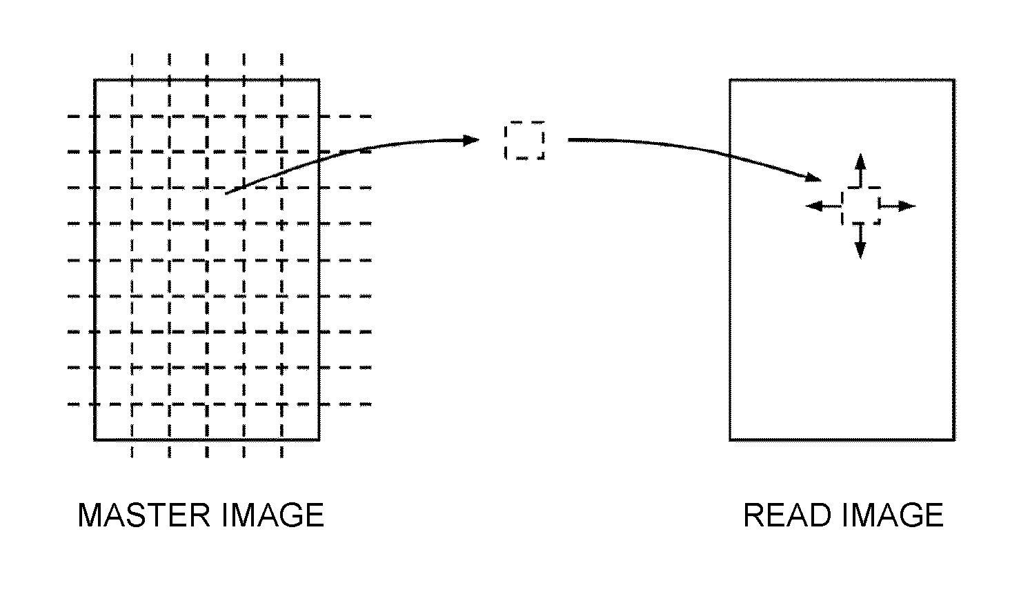
[0037]The following describes an embodiment of the present invention in detail with reference to the drawings. The embodiment describes a function for facilitating a setting of a threshold applied to a difference value between a read image and a master image in an image inspecting system including an image inspecting device that inspects an output result by comparing the read image obtained by reading the output result of an image formation output with the master image (an example of a reference image).

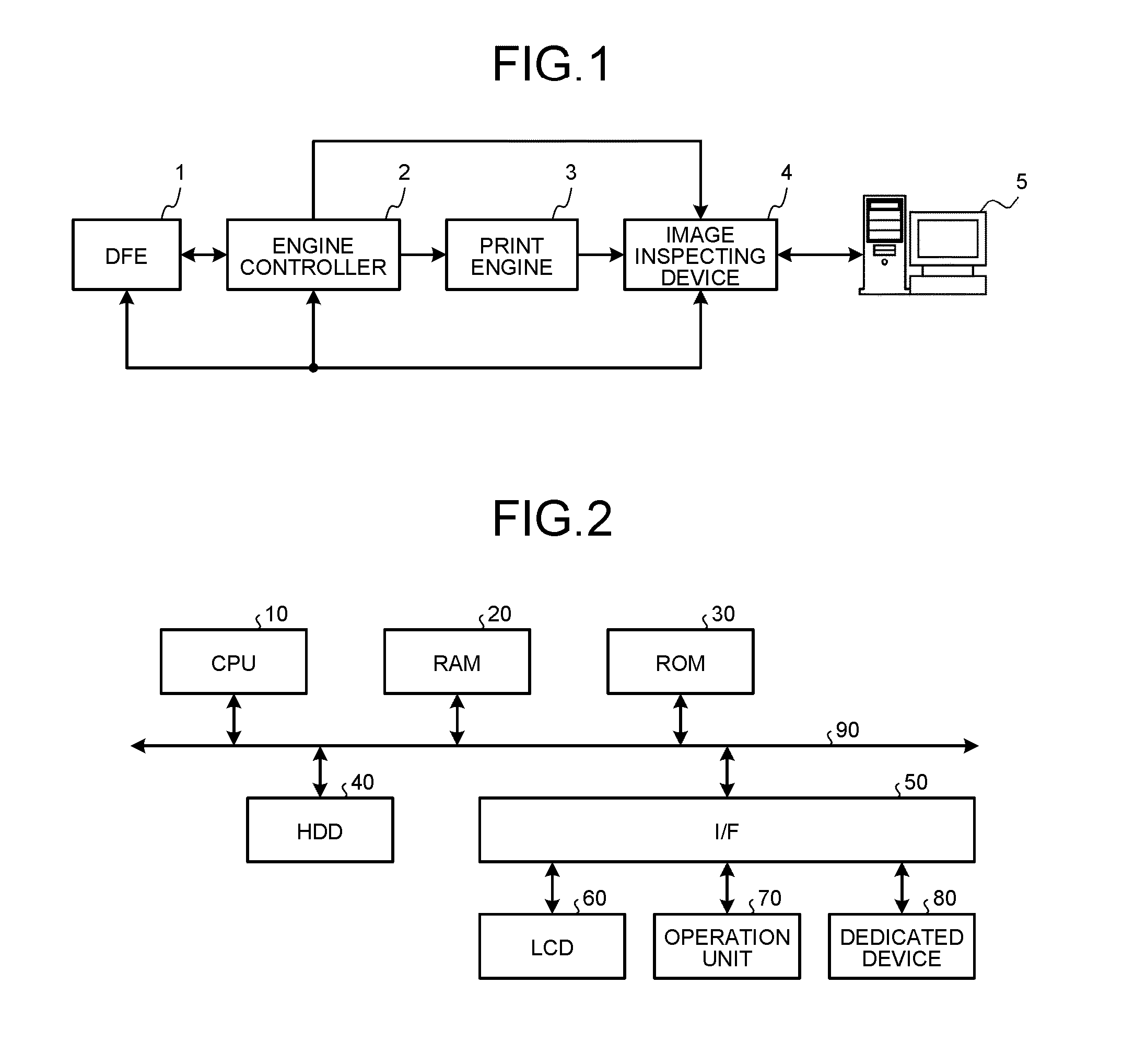
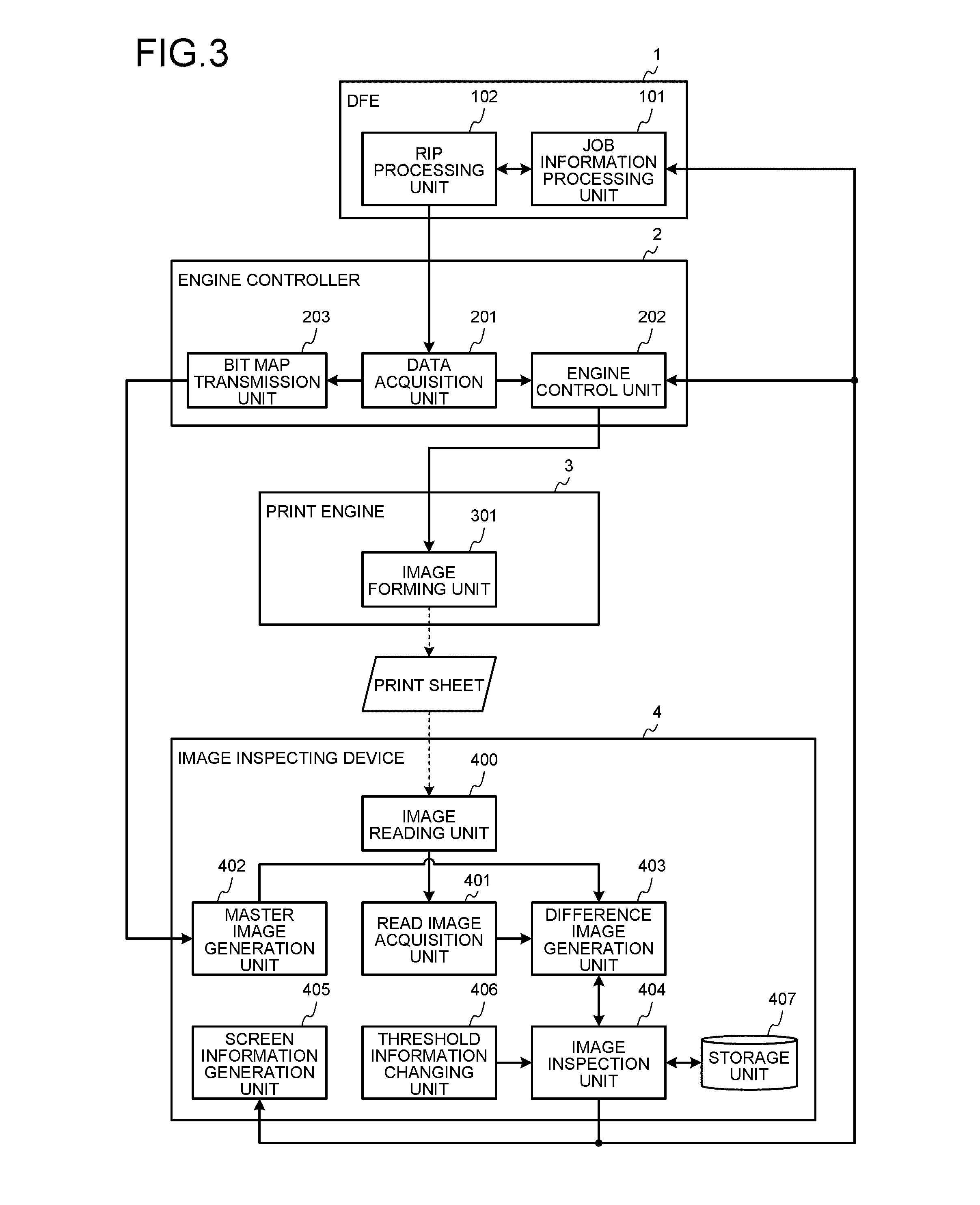
[0038]FIG. 1 is a diagram illustrating the entire structure of an image forming system according to the embodiment. As illustrated in FIG. 1, the image forming system according to the embodiment includes a digital front end (DFE) 1, an engine controller 2, a print engine 3, an image inspecting device 4, and an interface terminal 5. The DFE 1 is an image processing device that generates, based on a received print job, print data to be printed and output, specifically, bit map data as a...


PUM


Abstract

An image inspecting device includes: an image inspection unit that inspects a read image obtained by reading an image formed by an image formation output, based on threshold information including one or more types of thresholds and a difference image indicating a difference between the read image and a reference image generated based on print data of the image formation output, and specifies a defect portion; and a screen information generation unit that generates and outputs threshold adjustment screen information including a threshold image indicating each value of the thresholds and an inspection result image indicating an inspection result of the defect portion, and threshold adjustment result screen information including a threshold image and a reinspection result image using adjusted threshold information; and a threshold information changing unit that changes the threshold information to the adjusted threshold information based on a threshold information change input.

Description


Claims


Application Information

Patent Timeline
Owner RICOH KK
Why Eureka
Try Eureka