Sliding guide rail

Inactive Publication Date: 2015-10-01
INTER IKEA SYST
View PDF3 Cites 12 Cited by
  • Summary
  • Abstract
  • Description
  • Claims
  • Application Information

AI Technical Summary

Benefits of technology

[0007]Accordingly, the present invention seeks to mitigate, alleviate or eliminate one or more

Problems solved by technology

However, one major drawback of sliding assemblies is that it is difficult to achieve a satisfactory alignment of the cabinet rail relative the drawer rail, and consequently achieve a satisfactory alignment of the chest or cabinet relative the drawer.
In particular, alignment is crucial when the drawer is closed since a tilt of the drawer will not only contribute to a less aesthetic appearance, but also to reduced functionality and durability of the drawer.
In case the drawer is angled relative a horizontal plane, the load on one of the sliding assemblies will exceed the load of the opposite sliding assembly such that the unbalanced wear will lead

Method used


Image

  • Sliding guide rail
  • Sliding guide rail
  • Sliding guide rail

Examples


Example

[0037]Below, several embodiments of the invention will be described with references to the drawings. These embodiments are described in illustrating purpose in order to enable a skilled person to carry out the invention and to disclose the best mode. However, such embodiments do not limit the invention, but other combinations of the different features are possible within the scope of the invention.

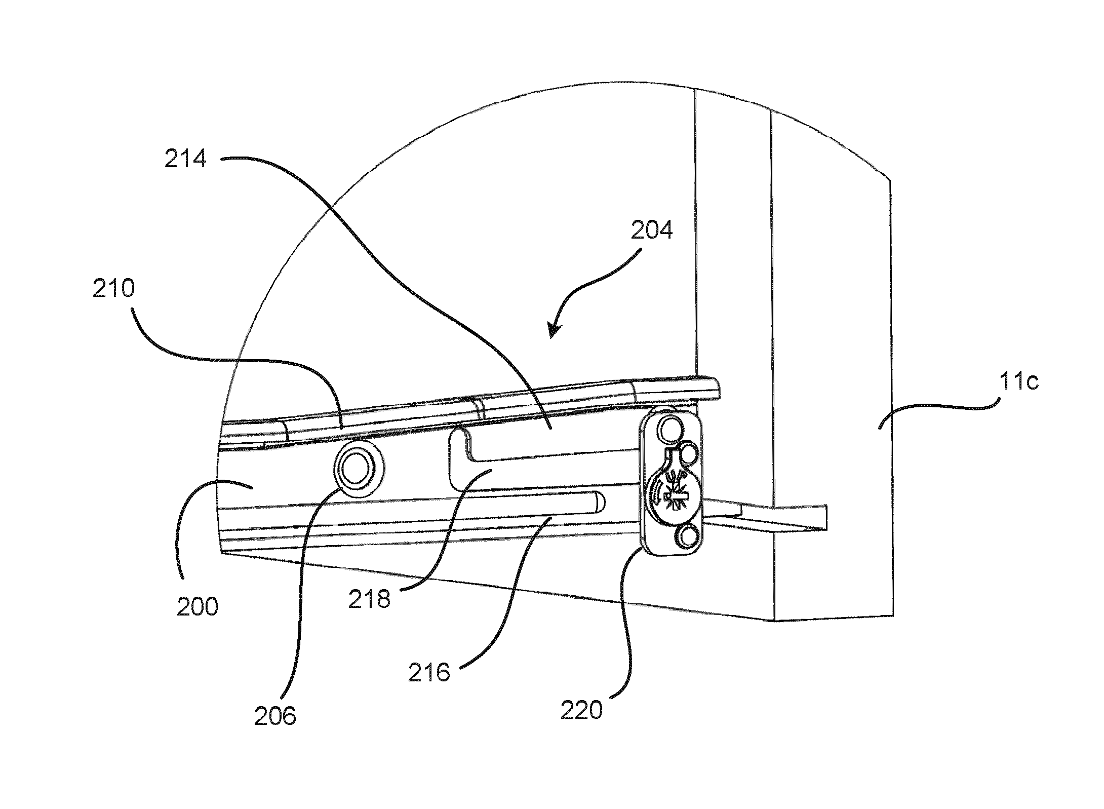
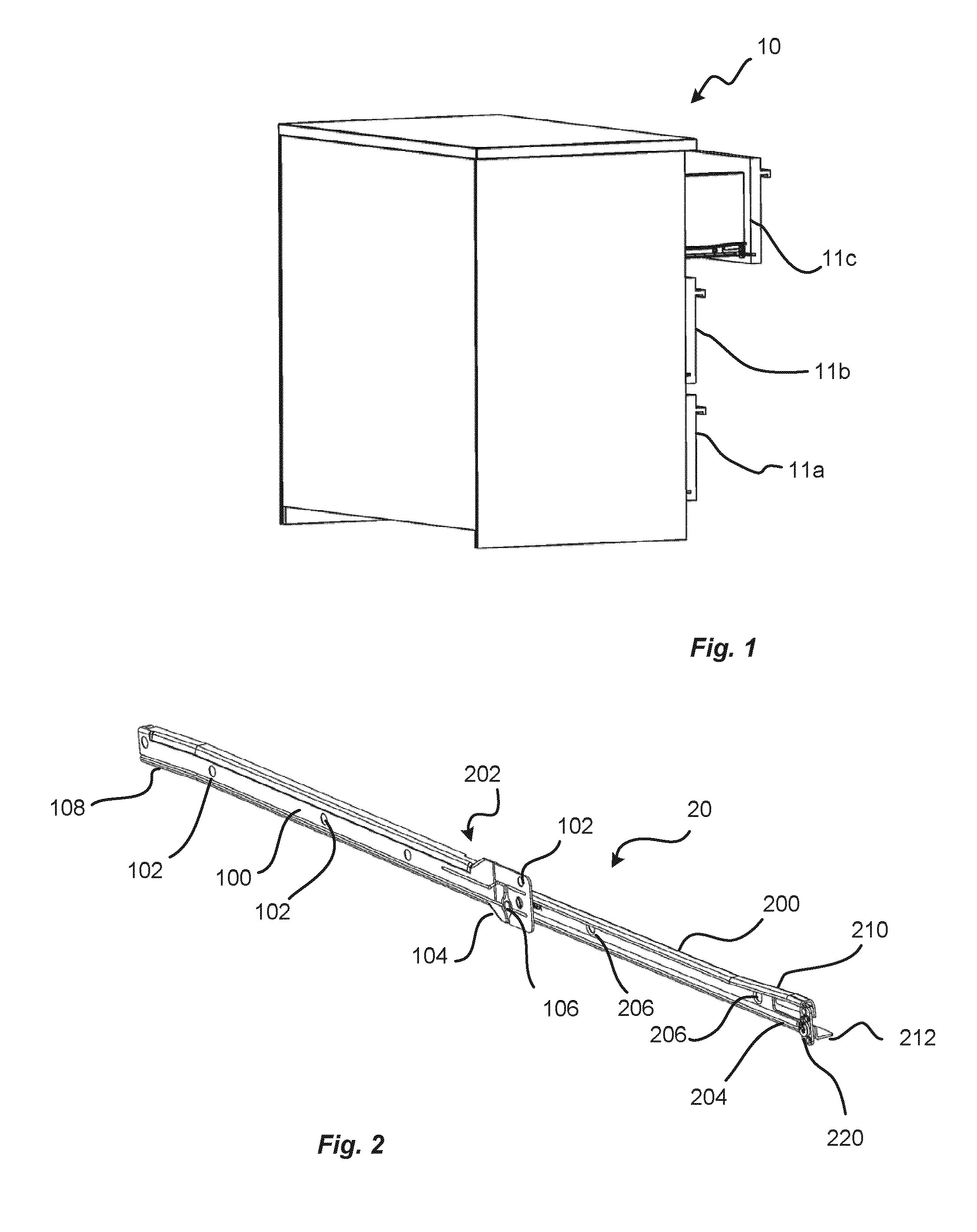
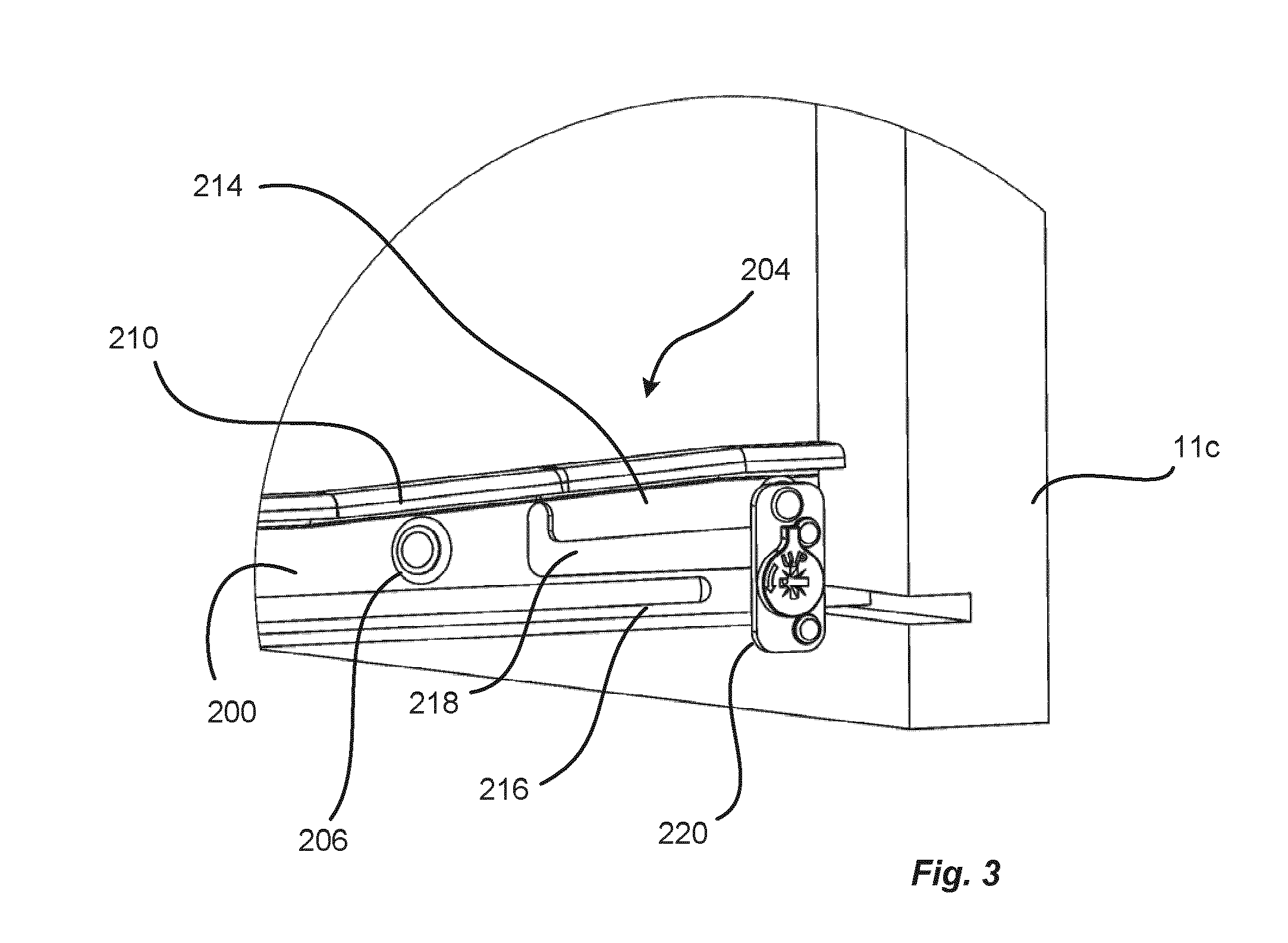
[0038]Starting with FIG. 1, a furniture carcass 10, such as a chest of drawers, including three drawers 11a, 11b, and 11c is shown. The upper drawer 11c is pulled out from the frame into a semi-opened position by means of a sliding rail assembly 20, which allows the drawer 11c to be pulled and pushed between an open and a closed position by a sliding motion. The sliding motion is provided by means of the sliding rail assembly 20, which is shown in further details in FIG. 2.

[0039]The sliding rail assembly 20 comprises a first rail 100 and a sliding guide rail 200. The first rail 100 has thr...


PUM

PropertyMeasurementUnit
Distanceaaaaaaaaaa
Sliding frictionaaaaaaaaaa

Abstract

A sliding guide rail (200) is provided. The sliding guide rail comprises means for attaching said rail (200) to a drawer (11a, 11b, 11c), a first surface (210) continuously extending from a first end (202) to a second end (204) of said rail (200), said first surface (210) being engageable with a sliding member of another rail (100), and an adjusting device (220, 320) capable of deforming said first surface (210) at said second end (204), such that the position of said first surface (210) at the second end (204) is displaceable relative to said means for attaching said rail.

Description

FIELD OF THE INVENTION[0001]The present invention relates to a sliding guide rail. More particularly, the present invention relates to a sliding guide rail for allowing sliding opening and closing movement of a drawer.BACKGROUND ART[0002]Sliding guide rails are commonly known for allowing smooth movement of drawers. Typically, a furniture carcass, such as a chest of drawers or a kitchen cabinet, includes a frame having an interior spacing in which a drawer is fitted. The drawer is held in place by means of guide rail assemblies, which preferably enable sliding movement to allow the drawer to move in and out from said furniture carcass in a substantially horizontal direction.[0003]First parts of rail assemblies are attached to opposite sides of the interior wall of the furniture carcass, and second parts of the rail assemblies are attached to opposite sides of the outer walls of the drawer. The drawer is then put into position by engaging the first parts of the rail assemblies with t...

Claims


Application Information

Patent Timeline
IPC IPC(8): F16C29/00A47B88/08A47B88/49
CPCA47B88/08F16C29/001A47B2210/0054A47B2230/0014A47B88/40A47B88/49Y10T29/49908
Inventor PETERSSON, CHRISTERHAKANSSON, PONTUS
Owner INTER IKEA SYST
Why Eureka
Try Eureka