Pulse splitter with dispersion compensation

Inactive Publication Date: 2012-07-05
KONINKLIJKE PHILIPS ELECTRONICS NV
View PDF1 Cites 0 Cited by
  • Summary
  • Abstract
  • Description
  • Claims
  • Application Information

AI Technical Summary

Benefits of technology

[0012]It would be advantageous to achieve an improved pulse splitter. In general, the invention preferably seeks to mitigate, alleviate or eliminate one or more of the above mentioned disadvantages singly or in any combination.

Problems solved by technology

In particular, problems

Method used


Image

  • Pulse splitter with dispersion compensation
  • Pulse splitter with dispersion compensation
  • Pulse splitter with dispersion compensation

Examples


Example

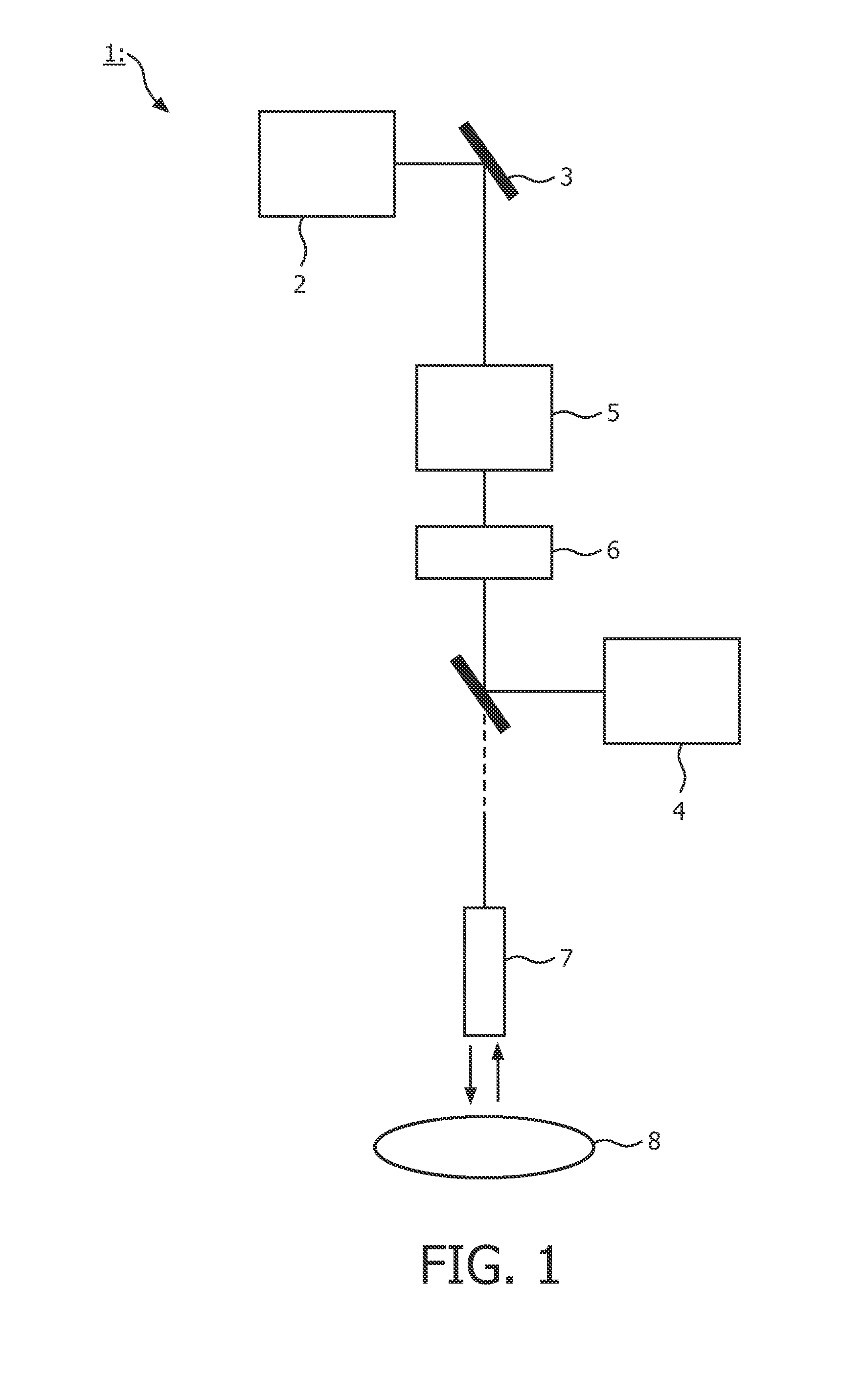
[0051]FIG. 1 is a schematic drawing of a system 1 for optical imaging of an object 8, e.g. tissue, according to the present invention. The system 1 comprises a pulsed irradiation source 2 adapted to emit irradiation pulses with a central wavelength λ. The source 2 is optically connected, i.e. through mirror 3 or similar devices, with a pulse splitter 5 according to the present invention. After the pulse splitting device 5, the sub-pulses (not shown in this Figure) are transmitted through a dispersion compensation device 6 (cf. FIG. 6 below) and via manipulating optics 7, e.g. focusing lenses and / or catheter arms, irradiated on the object 8. Radiation reflected from the object 8 (schematically indicated with the double arrows) is then detected in suitable optical detector 4 capable of detecting reflected radiation from the said object 8. In particular, the invention is advantageous for applications with femto second lasers in multi-photon microscopy of various kind of biological tiss...


PUM


Abstract

The present invention relates to a pulse splitting device (5) adapted to receive irradiation pulses (10) with a central wavelength (1) from a pulsed irradiation source (2) and output a plurality of sub-pulses (11,12, 15,17) for each incoming irradiation pulse. The received irradiation pulses and the pulse splitter (5) interacts so that a first and a second sub-pulse (11,12) are temporally separated by a first optical path length (OP1) in a first region and a second optical path length (OP2) in a second region, respectively. The first optical path length (OP1) times the group velocity dispersion (GVD1) with respect to wavelength in the first material, is balanced with the second optical path length (OP2) times the group velocity dispersion (GVD2) with respect to wavelength in the second material, so that the dispersion broadening of the first and the second sub-pulses (11,12) is substantially equal. This facilitates improved subsequent dispersion compensation by both sub-pulses.

Description

FIELD OF THE INVENTION[0001]The present invention relates to a pulse splitter with dispersion compensation, the pulse splitter being particularly suited for nonlinear optical imaging, especially multi-photon microscopy. The invention also relates to a corresponding optical imaging system and a corresponding method for imaging.BACKGROUND OF THE INVENTION[0002]Multi photon microscopy is a well-established technique in order to investigate biological tissue. It has the advantage over confocal fluorescence microscopy that it has a larger penetration depth in turbid media such as tissue, a smaller excitation load and a natural depth sectioning.[0003]The disadvantage of non-linear imaging is the small absorption cross section of fluorophores for two photon excitation. This could be compensated by increasing the excitation power, but the increase of power is limited in practice to a damage threshold for so-called bleaching at around 10 mW average power in a submicron focus with a conventio...

Claims


Application Information

Patent Timeline
IPC IPC(8): G02B27/12G01J1/04
CPCG02B27/106H01S3/0057G02B27/144G02B27/126
Inventor 'T HOOFT, GERTHORIKX, JEROEN JAN LAMBERTUS
Owner KONINKLIJKE PHILIPS ELECTRONICS NV
Why Eureka
Try Eureka