Device Proximity Detection

a technology of proximity detection and devices, applied in the direction of receiving monitoring, synchronisation arrangement, instruments, etc., to achieve the effect of preventing or reducing relay attacks

Inactive Publication Date: 2015-10-01
GOOGLE LLC
View PDF4 Cites 7 Cited by
  • Summary
  • Abstract
  • Description
  • Claims
  • Application Information

AI Technical Summary

Benefits of technology

[0003]According to an embodiment of the disclosed subject matter, a method of detecting proximity between two communicating devices is disclosed. An embodiment of the method uses inter-frame space parameters specified by a wireless protocol (e.g. Bluetooth Low Energy (LE)) to perform proximity detection and may be used to prevent or mitigate relay attacks.

Problems solved by technology

It may be difficult, however, to ensure that communication between two devices actually occurs with those devices in proximity of one another, since the communication may be vulnerable to an unsophisticated relay attack that imitates the proximity between devices.

Method used


Image

  • Device Proximity Detection
  • Device Proximity Detection
  • Device Proximity Detection

Examples


Embodiment Construction

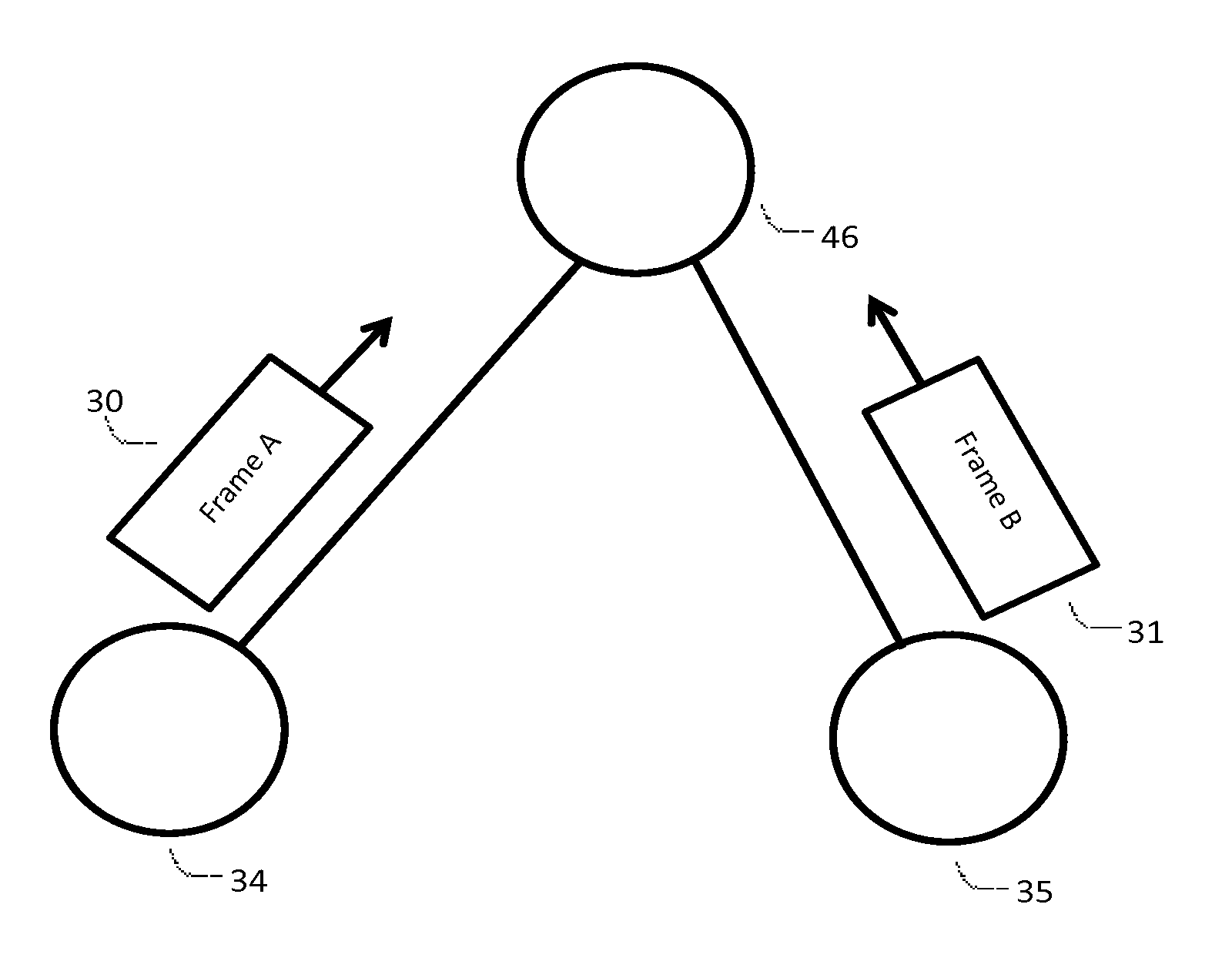
[0015]Generally, techniques and systems for detecting proximity between two communicating devices are disclosed. Proximity may be determined by measuring deviation from standardized signal timing specifications. In some configurations, the proximity may be determined based upon an elapsed time value and the speed of light, thus setting an upper bound on the possible distance between two devices that are presumed to be in proximity to one another.

[0016]A method is presented that uses characteristics of wireless protocols (e.g. Bluetooth Low Energy (LE) protocol) and physical properties associated with data communication (e.g. the speed of light) to ensure that communicating devices are in proximity with one another. Bluetooth LE technology is ubiquitous technology and can be used to do proximity detection. Techniques and systems as disclosed herein also may prevent or mitigate relay attacks by devices faking proximity.

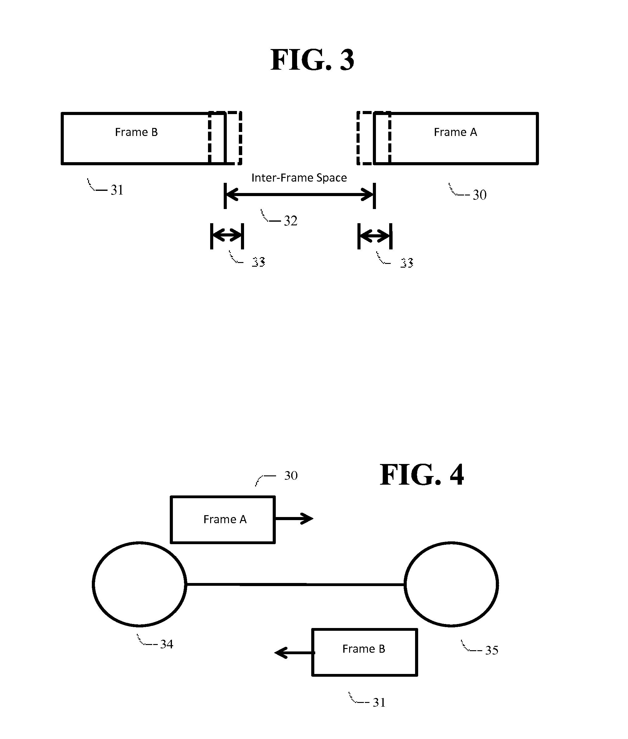
[0017]Embodiments described herein use data framing characteristic...


PUM


Abstract

A method for detecting proximity of two communicating devices is disclosed. Proximity may be determined by measuring deviation from standardized signal timing specifications. An embodiment uses inter-frame space parameters specified by the Bluetooth Low Energy protocol to do proximity detection, and presents a solution that may prevent or mitigate relay attacks. The method offers the advantage that the use of an existent frame timing protocol eliminates the need for specific hardware or firmware modifications.

Description

BACKGROUND[0001]Detecting proximity between portable computing devices is increasingly useful as the number of uniquely identifiable devices that communicate through networked communications continues to increase, and the use of such devices continues to proliferate. Examples where proximity detection is important include unlocking a door, paying in a store with a mobile device, accessing secure computing resources, and the like.[0002]Some applications, such as payment systems, require a high level of security. Existing security methods may be adequate to ensure the identity of the devices, and the confidentiality of the data transmitted locally. It may be difficult, however, to ensure that communication between two devices actually occurs with those devices in proximity of one another, since the communication may be vulnerable to an unsophisticated relay attack that imitates the proximity between devices.BRIEF SUMMARY[0003]According to an embodiment of the disclosed subject matter,...

Claims


Application Information

Patent Timeline
Patent Type & Authority Applications(United States)
IPC IPC(8): H04B17/27H04W4/02H04W56/00
CPCH04B17/27H04W4/023H04W56/0015H04L43/00H04L69/28H04J3/0679H04L43/0852H04L43/04H04L67/52G06F21/00G06F21/31G06F21/32G06K15/00G06K15/402G06K15/4095H04N1/00347H04N1/00838H04N1/00973
Inventor FUCCI, MARCO
Owner GOOGLE LLC
Why Eureka
Try Eureka