Roller bearing with modular shoulders

a technology of rolling bearings and shoulders, applied in the direction of roller bearings, shaft assemblies, mechanical instruments, etc., can solve the problems of large energy loss, large increase of friction between rollers and rings, and high precision mechanical machining with narrow tolerances, so as to achieve scale-saving effects

Inactive Publication Date: 2015-10-08
AB SKF
View PDF7 Cites 5 Cited by
  • Summary
  • Abstract
  • Description
  • Claims
  • Application Information

AI Technical Summary

Benefits of technology

[0010]Moreover, the same inner and outer rings may be used for bearings having different shoulder configurations according to the various operative needs, thus allowing considerable economies of scale.
[0011]Finally, the contact friction between revolving bodies and lateral shoulders of the bearing rings is considerably reduced due to both the type of materials used and because pockets for containing lubricating fluids may be provided on the side of the shoulders facing the inner bearing.

Problems solved by technology

This solution has the drawback of requiring high-precision mechanical machining with narrow tolerances, which are therefore very costly, in order to obtain the shoulders.
Furthermore, the rollers touch the shoulders because of possible axial movements of the rollers themselves, thus producing a relatively high increase of the friction between rollers and rings, with a consequent undesired heating of the bearing and undesired energy losses.
U.S. Pat. No. 5,000,588 does not completely solve these problems.

Method used


Image

  • Roller bearing with modular shoulders
  • Roller bearing with modular shoulders
  • Roller bearing with modular shoulders

Examples


Embodiment Construction

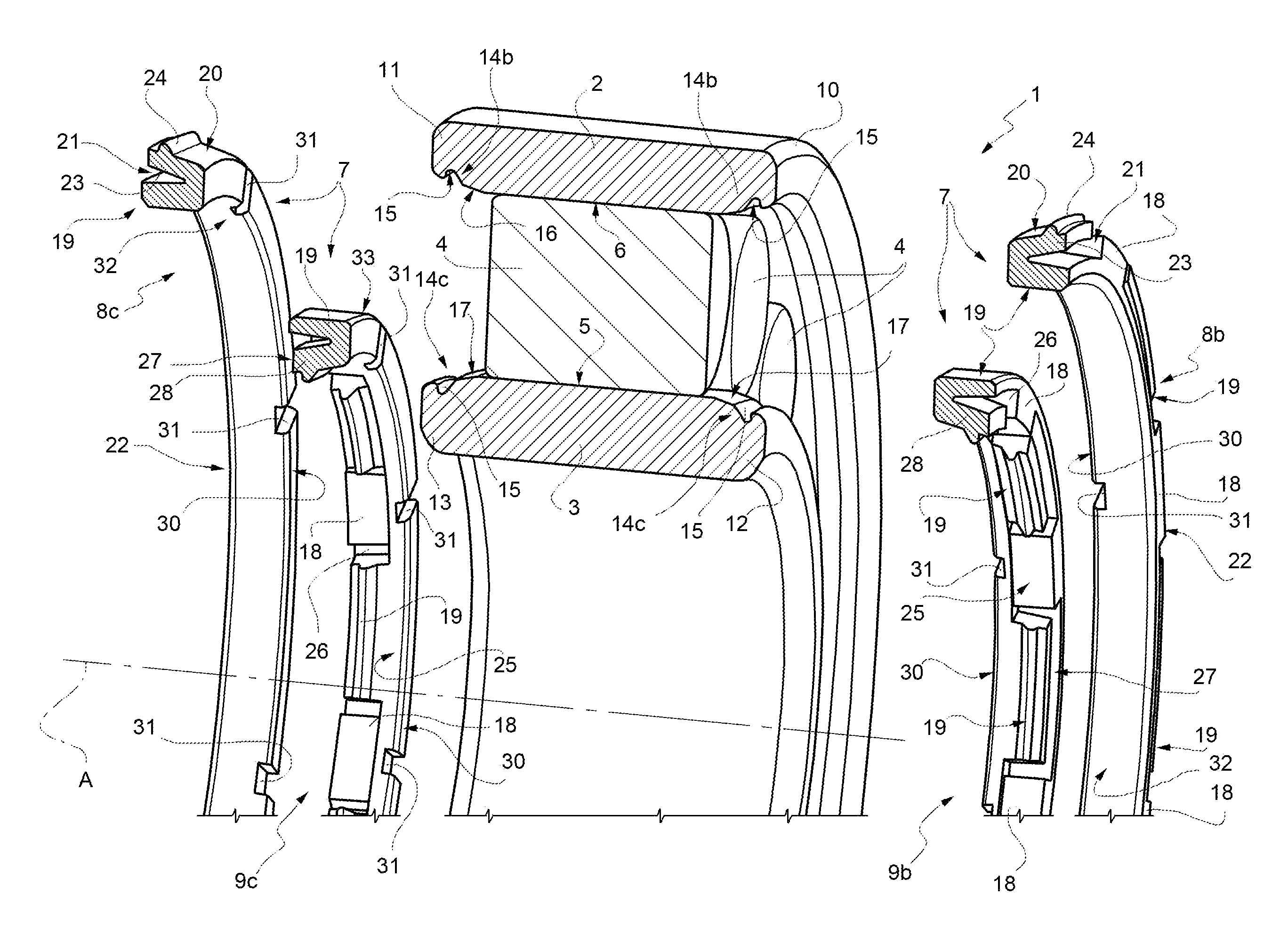
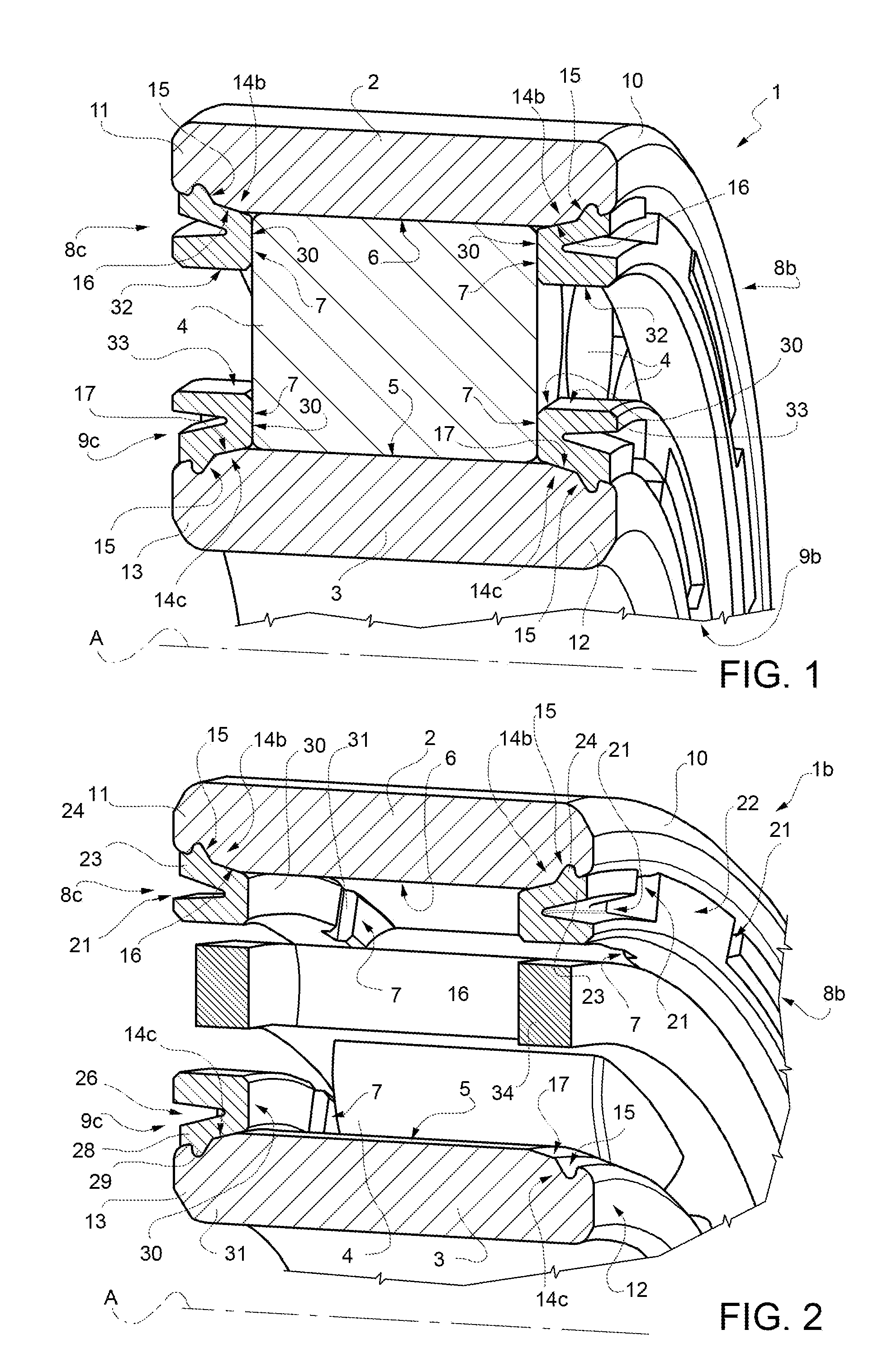
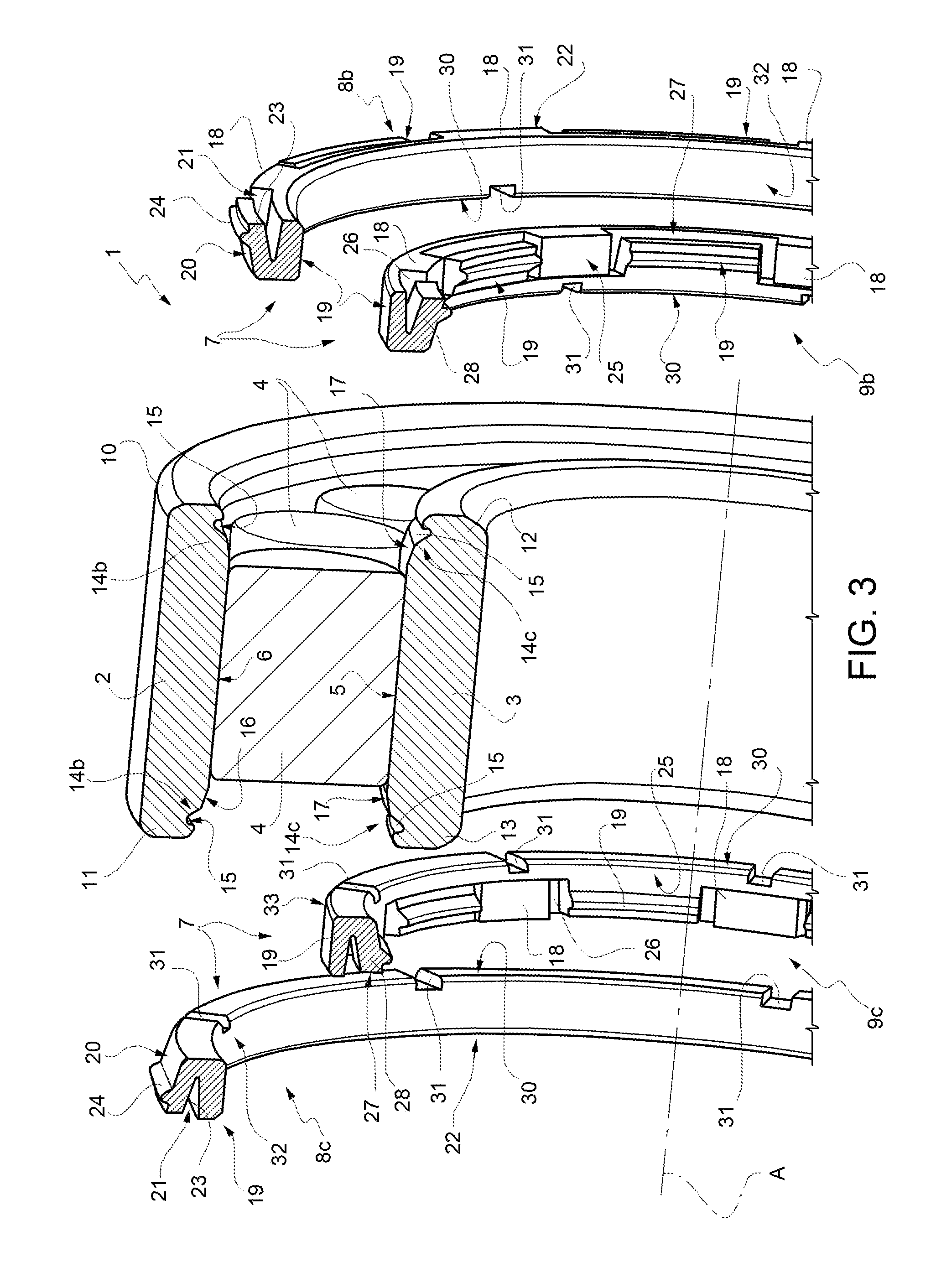
[0017]With reference to FIGS. 1 and 3 to 7, reference numeral 1 indicates as a whole a rolling bearing of the roller type, comprising a radially outer ring 2, a radially inner ring 3 and a plurality of revolving bodies defined by rollers 4 interposed between the radially outer ring 2 and the radially inner ring 3 and grouped, in the non-limiting example shown, into a crown of revolving bodies. Obviously, the following description may also apply to bearings with two crowns of rollers.

[0018]Rollers 4 engage a radially outer lateral surface 5 of the inner ring 3 and a radially inner lateral surface 6 of the outer ring 2 facing each other and laterally held, in a direction parallel to a relative rotation axis A (shown not in scale in the accompanying figures for simplicity) between the inner 3 and outer 4 rings, by respective axial shoulders 7 integrally carried by either one or both the inner and outer rings 3 and 2; in the example shown, there are four shoulders 7, two being integrall...


PUM


Abstract

A rolling bearing is provided that includes an outer ring, an inner ring, and a plurality of rollers disposed between the outer and inner rings to engage a radially outer lateral surface of the inner ring and a radially inner lateral surface of the outer ring and being laterally held, in a direction parallel to a relative rotation axis (A) between the rings, by respective axial shoulders. The axial shoulders each consist of an annular element made of synthetic plastic material as an independent element from the rings that engages in a snapping manner either the inner ring or the outer ring; the inner and outer rings being provided, at their respective radially outer and inner lateral surfaces and at opposite axial ends thereof, with snapping locking seats for the annular elements made of synthetic plastic material each including a continuous annular groove.

Description

TECHNICAL FIELD OF THE INVENTION[0001]The present invention relates to a rolling bearing of the roller type, which is cost-effective to be manufactured and which allows to reduce the friction between the revolving bodies, defined by rollers, generally of the cylindrical type, and the radially inner and outer rings of the bearing.TECHNICAL BACKGROUND[0002]In rolling bearings of the roller type, the revolving bodies, generally consisting of cylindrical rollers, are laterally held in axial direction and towards opposite frontal ends of the inner and outer rings of the bearing, by respective shoulders obtained by mechanical machining directly on the radially inner and radially outer surfaces of the rings, on which the rollers roll in use.[0003]Therefore, according to this solution, the lateral axial holding shoulders of the rollers form an integral part of the rolling tracks of the rollers.[0004]This solution has the drawback of requiring high-precision mechanical machining with narrow ...

Claims


Application Information

Patent Timeline
Patent Type & Authority Applications(United States)
IPC IPC(8): F16C33/58F16C19/26F16C33/66
CPCF16C33/586F16C19/26F16C33/6651F16C2226/74F16C33/6614F16C33/605
Inventor MOLA, ROBERTORESTIVO, RICCARDOSANTANGELO, PIEROSCALTRITI, GIANPIERO
Owner AB SKF
Why Eureka
Try Eureka