Robotic System and Method for Reorienting a Surgical Instrument Moving Along a Tool Path

a robotic system and surgical instrument technology, applied in the field of robotic systems, can solve problems such as difficulty in providing a robotic system able, and the possibility of collision of instruments

Active Publication Date: 2015-10-15
STRYKER CORP
View PDF10 Cites 24 Cited by
  • Summary
  • Abstract
  • Description
  • Claims
  • Application Information

AI Technical Summary

Problems solved by technology

Some robotic systems are not traditional robots in that once activated, they do not automatically move the attached instrument along a pre-programmed path of travel.
To date though, it has been difficult to provide a robotic system able to, during the performance of a sin...

Method used


Image

  • Robotic System and Method for Reorienting a Surgical Instrument Moving Along a Tool Path
  • Robotic System and Method for Reorienting a Surgical Instrument Moving Along a Tool Path
  • Robotic System and Method for Reorienting a Surgical Instrument Moving Along a Tool Path

Examples


Embodiment Construction

I. Overview

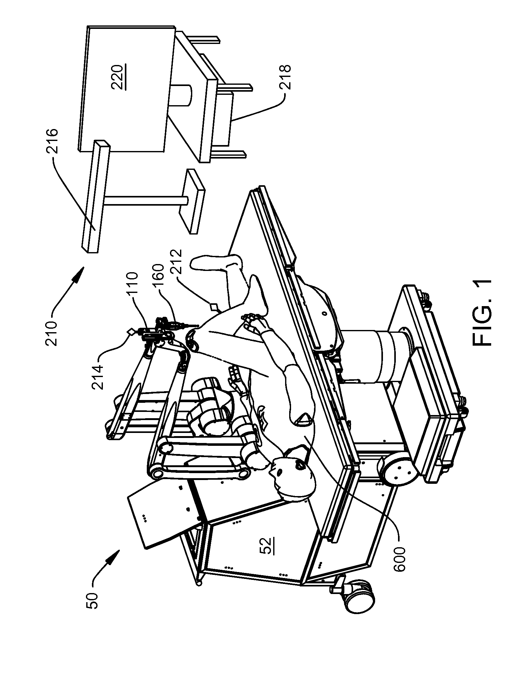
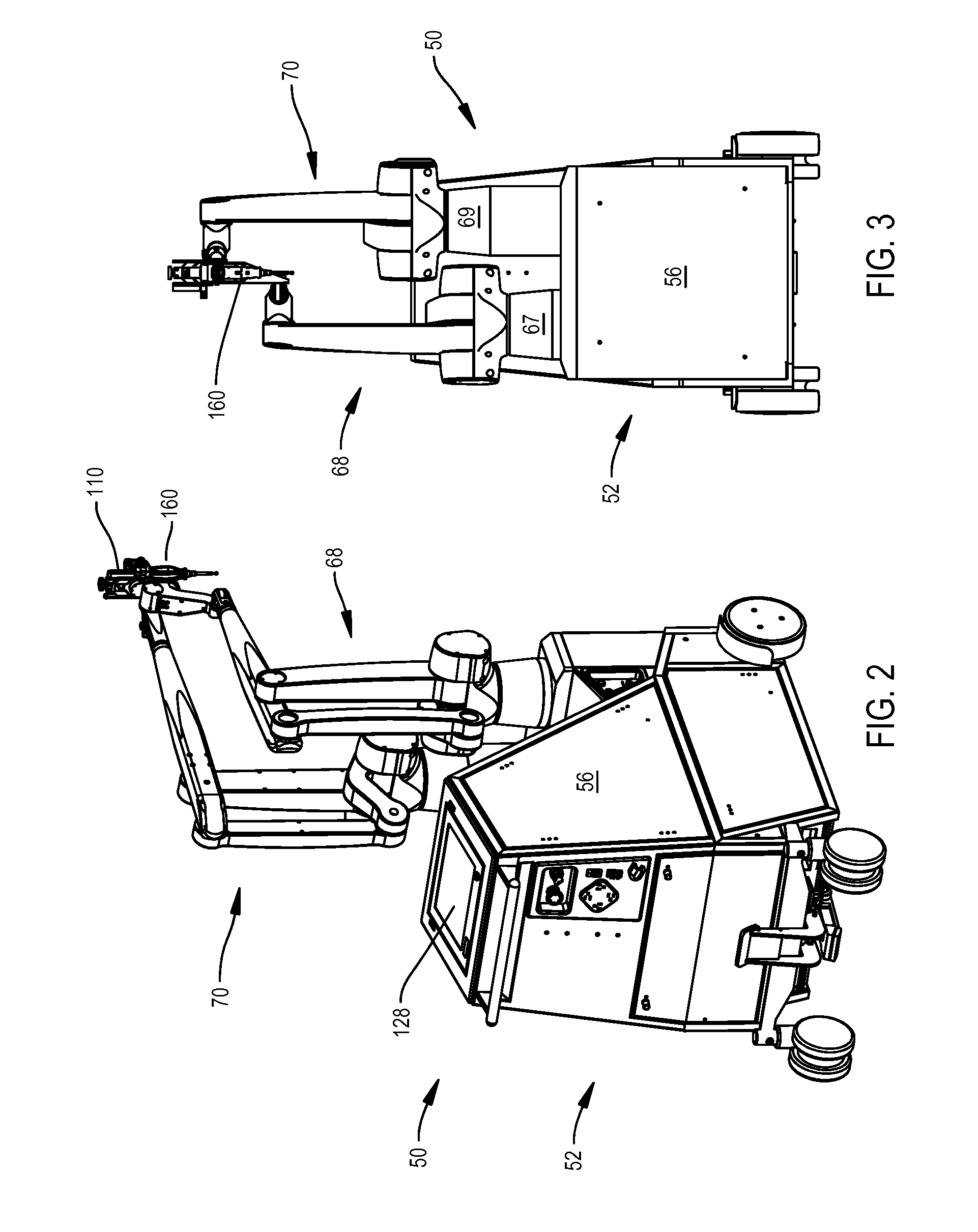
[0054]This invention relates generally to a new and useful surgical manipulator that positions a surgical instrument or tool on or in the patient. The surgical manipulator positions the surgical instrument so that the end of instrument that is to be applied to the tissue is only applied to the tissue to which the instrument should be applied.

[0055]The manipulator can be operated in either a manual mode or a semi-autonomous mode. When the manipulator is operated in the manual mode, the manipulator monitors the forces and torques the practitioner places on the instrument in order to position the instrument. These forces and torques are measured by a sensor that is part of the manipulator. In response to the practitioner applied forces and torques, the manipulator essentially moves the instrument in real time. The movement of the instrument by the manipulator can therefore be considered to be movement of the instrument that emulates the desired positioning of the instrument ...


PUM


Abstract

Robotic system and method for positioning an energy applicator extending from a surgical instrument. The robotic system includes a surgical manipulator operable in a manual mode or a semi-autonomous mode. The surgical manipulator moves the energy applicator along a tool path in the semi-autonomous mode, monitors output of a force/torque sensor as the energy applicator moves along the tool path, and reorients the surgical instrument based on the output in response to a user applying reorienting forces and torques to the surgical instrument.

Description

CROSS-REFERENCE TO RELATED APPLICATIONS[0001]This application is a continuation of U.S. non-provisional application Ser. No. 14 / 208,293 filed on Mar. 13, 2014, which is a continuation-in-part of U.S. non-provisional application Ser. No. 13 / 958,070 filed on Aug. 2, 2013, which claims the benefit of U.S. provisional patent application No. 61 / 679,258, filed on Aug. 3, 2012, and U.S. provisional patent application No. 61 / 792,251, filed on Mar. 15, 2013. U.S. non-provisional application Ser. No. 14 / 208,293 also claims the benefit of U.S. provisional patent application No. 61 / 792,251, filed on Mar. 15, 2013. The advantages and disclosures of each of the applications set forth above are hereby incorporated by reference in their entirety.FIELD[0002]This invention relates generally to a robotic system. More particularly, this invention relates to a robotic system and method for reorienting a surgical instrument moving along a tool path.BACKGROUND[0003]Recently, medical practitioners have fou...

Claims


Application Information

Patent Timeline
IPC IPC(8): A61B19/00
CPCA61B19/2203A61B2019/507A61B2019/2223A61B2019/2207A61B17/16B25J9/009B25J9/1633G05B2219/40191G05B2219/45117A61B18/148A61B2018/00565A61B2018/00601A61B34/32A61B34/20A61B34/37A61B2090/066A61B2034/107G16H40/63A61B34/30B25J13/00A61B17/1626A61B34/70B25J13/085A61B2034/2046A61B34/76
Inventor BOWLING, DAVID GENESTUART, JOHN MICHAELCULP, JERRY A.MALACKOWSKI, DONALD W.MOCTEZUMA DE LA BARRERA, JOSE LUISROESSLER, PATRICKBEER, JOEL N.KETCHEL, JOHN
Owner STRYKER CORP
Why Eureka
Try Eureka