Light source device

a technology of light source and guide plate, which is applied in the direction of instruments, lighting and heating apparatus, mechanical apparatus, etc., can solve the problems of increasing the number of components in the unit, difficult to satisfy, and complicated assembly, and achieves secure viewing angle characteristics, improved dimming characteristics, and high front luminance

Active Publication Date: 2015-10-15
PANASONIC INTELLECTUAL PROPERTY MANAGEMENT CO LTD
View PDF8 Cites 14 Cited by
  • Summary
  • Abstract
  • Description
  • Claims
  • Application Information

AI Technical Summary

Benefits of technology

[0020]The light guide plate according to the present invention secures viewing angle characteristics and has high front luminance, in which the dimming characteristics are improved.

Problems solved by technology

However, in order to secure viewing angle characteristics and suppressing luminance non-uniformity in an angular direction as well as to improve dimming characteristics (area light-emitting characteristics), it is difficult to satisfy conflicting characteristics of viewing angle characteristics, luminance non-uniformity and dimming characteristics as the tip angle T of the prisms is one kind, and it is necessary to use two pieces of expensive prism sheets, which causes problems that the number of components in the unit is increased and the assembly becomes complicated.

Method used


Image

  • Light source device
  • Light source device
  • Light source device

Examples


embodiment 1

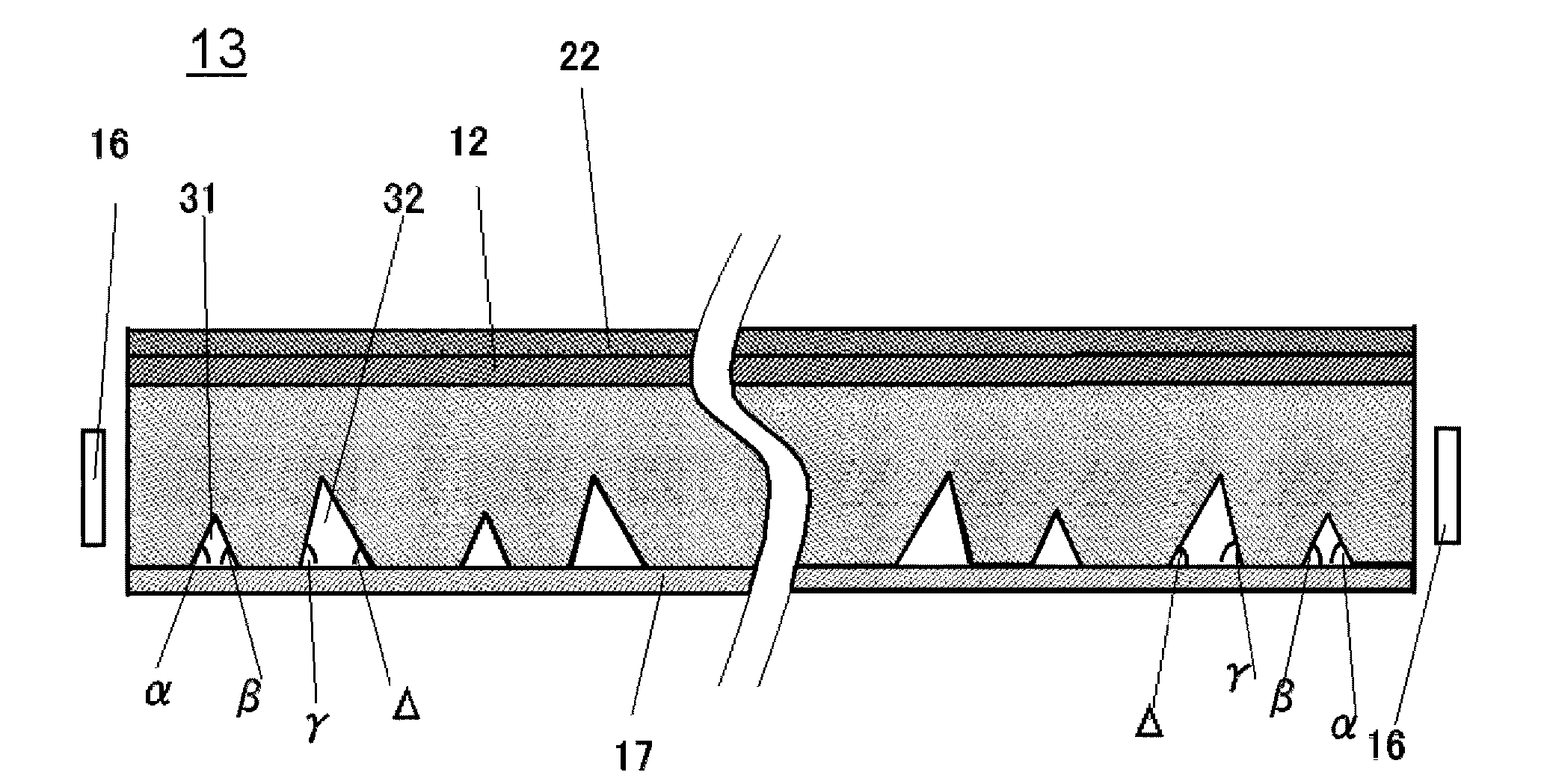
[0069]Embodiment 1 of the present invention will be explained with reference to FIG. 1 and FIGS. 2A to 2E.

[0070]In the light guide plate 13 according to Embodiment 1, angles of the first prisms 31 and the second prisms 32 in FIG. 1 are respectively, the angle α: 42°, the angle β: 62°, the angle γ: 68° and the angle Δ: 48°, and the first prisms 31 and the second prisms 32 are repeatedly provided.

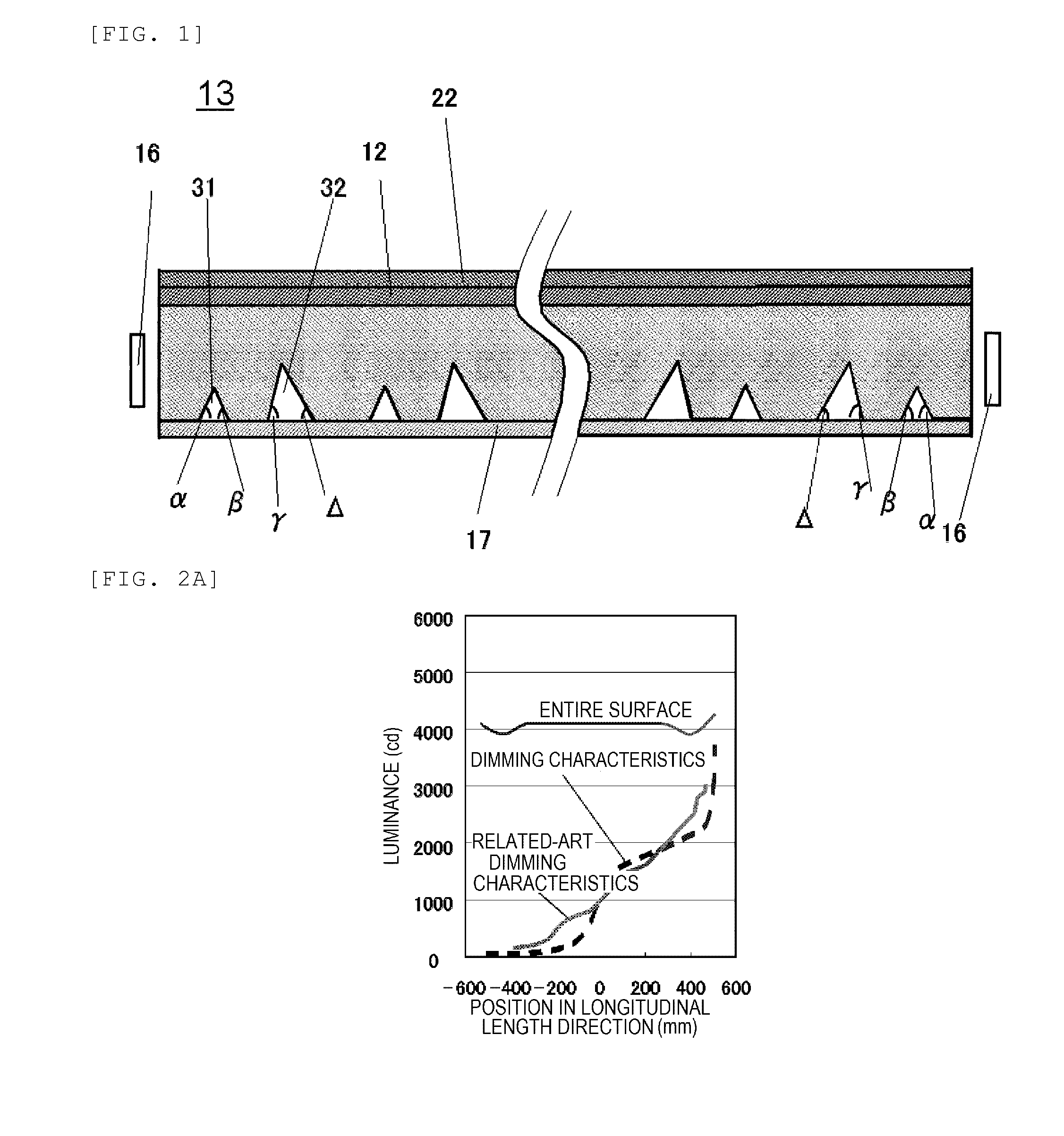
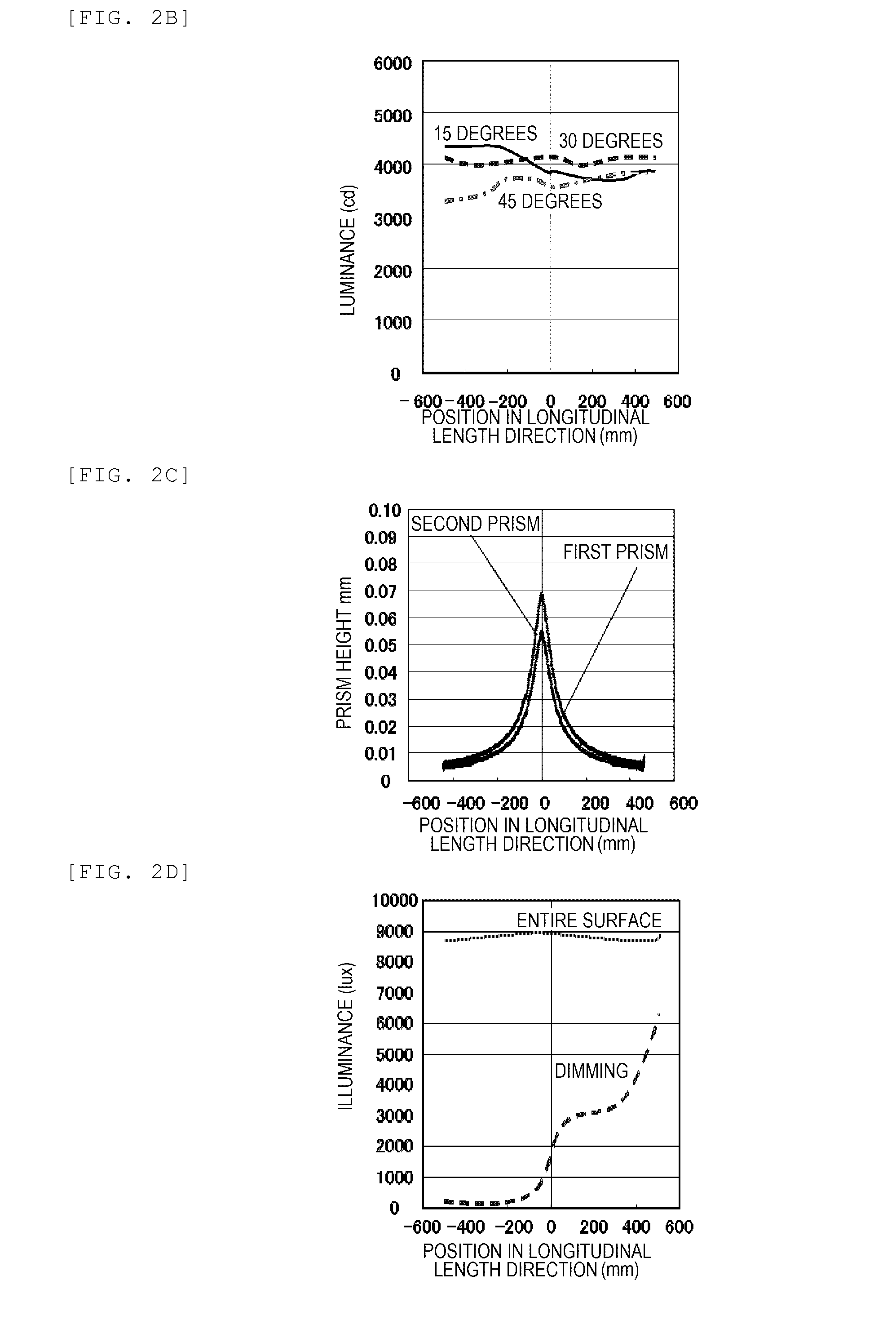
[0071]FIG. 2A to 2E show optical simulation results of the light guide plate 13 in the above case.

[0072]FIG. 2A shows a luminance characteristic graph, in which a horizontal axis indicates the length in the longitudinal direction of the light guide plate 13 and a vertical axis indicates the luminance. FIG. 2A shows luminance distribution obtained when both sides of LEDs 16 emit light. The dimming characteristics were also measured by allowing the LEDs 16 at one side of the light guide plate 13 to emit light.

[0073]As shown in FIG. 2A, it is found that the luminance uniformity is good when the ...

embodiment 2

[0078]Embodiment 2 of the present invention will be explained with reference to FIG. 1 and FIGS. 3A to 3E.

[0079]In the light guide plate 13 according to Embodiment 2, angles of the first prisms 31 and the second prisms 32 in FIG. 1 are respectively, the angle α: 52°, the angle β: 52°, the angle γ: 72° and the angle Δ: 32°, and the first prisms 31 and the second prisms 32 are repeatedly provided.

[0080]FIG. 3A to 3E show optical simulation results in the above prism shapes. The vertical axes and the horizontal axes of the drawings indicate the same as those in FIG. 2A to 2E.

[0081]FIG. 3A is a luminance characteristic graph. A horizontal axis indicates the longitudinal direction length of the light guide plate 13 and a vertical axis indicates the luminance. The luminance uniformity on the entire surface is good and the dimming characteristics are better than related-art dimming characteristics.

[0082]FIG. 3B is a luminance-angle characteristic graph, in which the almost equivalent chara...

embodiment 3

[0086]Embodiment 3 of the present invention will be explained with reference to FIG. 1 and FIGS. 4A to 4E. In the light guide plate 13 according to Embodiment 3, angles of the first prisms 31 and the second prisms 32 in FIG. 1 are respectively, the angle α: 52°, the angle β: 52°, the angle γ: 75° and the angle Δ: 27°, and the first prisms 31 and the second prisms 32 are repeatedly provided.

[0087]FIG. 4A to 4E show optical simulation results in the prism shapes in this case. The vertical axis and the horizontal axis of the drawings indicate the same as those in FIG. 2A to 2E.

[0088]FIG. 4A is a luminance characteristic graph. A horizontal axis indicates the longitudinal direction length of the light guide plate 13 and a vertical axis indicates the luminance. The luminance uniformity on the entire surface is good and the dimming characteristics are better than related-art dimming characteristics.

[0089]FIG. 4B is a luminance-angle characteristic graph, in which the almost equivalent cha...


PUM


Abstract

A light source device including a light guide plate and a light source, in which the light guide plate includes an incident surface on which light emitted from the light source is incident, an emission surface emitting light incident from the incident surface, and a propagating reflection surface which is a surface opposite to the emission surface and which propagates and reflects the light incident from the incident surface toward the emission surface, the propagating reflection surface has approximately V-shaped grooves and the V-shaped grooves have two kinds of grooves.

Description

TECHNICAL FIELD[0001]The present invention relates to a light guide plate used for an edge-light type backlight for a liquid crystal panel and for illumination.BACKGROUND ART[0002]A liquid crystal display device commonly requires a separate light source such as a backlight as it is not a self-luminous device. A backlight unit chiefly includes a light source and a light guide plate guiding light emitted from the light source to realize surface emission.[0003]In general, the backlight unit is categorized into a direct-type backlight and an edge-light type backlight according to the position of the light source. In the direct-type backlight, a large number of light sources such as cold cathode lamps or LEDs (light emitting diodes) are provided just under a liquid crystal panel, in which light emitted from the light sources is diffused through plural optical sheets and irradiated to the liquid crystal display device panel. In the edge-light type backlight, a light guide plate is used, i...

Claims


Application Information

Patent Timeline
Patent Type & Authority Applications(United States)
IPC IPC(8): F21V8/00
CPCG02B6/0061G02B6/0051G02B6/0038
Inventor KIKUCHI, TAKANORIKUSAKA, YUSUKEFUJITA, MASARUKANAYAMA, YOSHIHIKOMOCHIDA, SHOHROHITO, MASAMI
Owner PANASONIC INTELLECTUAL PROPERTY MANAGEMENT CO LTD
Why Eureka
Try Eureka